Portable positive-pressure automatic resuscitator

A resuscitator and portable technology, applied in the field of medical devices, can solve the problems of inconvenient carrying, low safety, and large volume

Active Publication Date: 2014-12-24
山西虹安科技股份有限公司
View PDF6 Cites 1 Cited by
  • Summary
  • Abstract
  • Description
  • Claims
  • Application Information

AI Technical Summary

Problems solved by technology

[0003] The present invention mainly aims at the problems of low safety, low degree of automation, relatively large volume, inconv...

Method used


Image

  • Portable positive-pressure automatic resuscitator
  • Portable positive-pressure automatic resuscitator
  • Portable positive-pressure automatic resuscitator

Examples


Embodiment 1

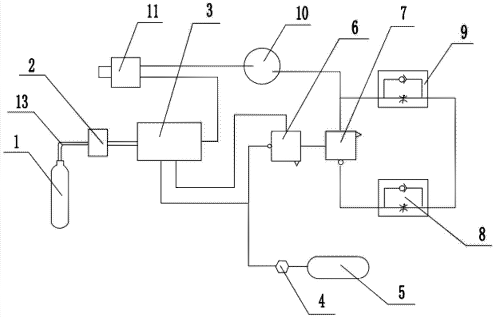
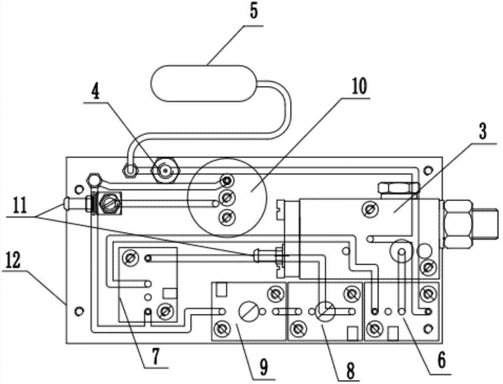
[0037] Such as figure 1 with figure 2 As shown, a portable positive pressure automatic resuscitator includes an oxygen cylinder 1, a pressure reducer group 2, a control device 3, a quantitative valve 4, an accumulator 5, a No. I gate 6, a No. II gate 7, and a No. I One-way throttle valve 8, No. II one-way throttle valve 9, pressure controller 10, air supply valve group 11 and air circuit board 12;

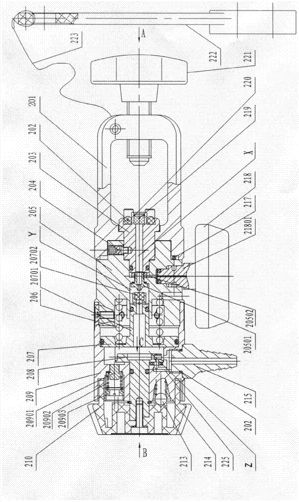
[0038] Such as image 3 , Figure 4 , Figure 5 with Image 6 As shown, the pressure reducer group 2 includes a connecting frame 201, a sealing ring 202, a connecting piece 203, a positioning pin 204, a valve seat group 205, a pressure reducer spring 206, a slide valve group 207, a quantitative control valve 208, and a valve body Group 209, handwheel 210, positioning ball 213, positioning spring 214, mouthpiece II215, U-shaped card 217, pressure gauge 218, pressure gauge joint 21801, filter element 219, snap spring 220, fastening wrench 221, wrench 222, connection line 223 a...


PUM


Abstract

The invention belongs to the technical field of medical apparatuses and particularly relates to a portable positive-pressure automatic resuscitator. The invention mainly solves the problems that the safety of the existing resuscitator is low, the automation level is low, the size is larger, the resuscitator is inconvenient to carry and the emergency performance is poor. The technical scheme is that the portable positive-pressure automatic resuscitator comprises parts such as a pressure reducer group, a control device and a proportional valve; the pressure reducer group is connected with the control device, the control device is connected with an air supply valve group, a No.1 NOT gate is connected with a No.2 NOT gate, an air outlet of the No.2 gate is connected with a No.2 one-way throttle valve, an air outlet end of the No.2 NOT gate is further connected with an air inlet E of a pressure controller, the pressure controller is connected with the air supply valve group, a control end of the No.2 NOT gate is connected with a No.1 one-way throttle valve, the No.1 one-way throttle valve is connected with the No.2one-way throttle valve, and the throttling direction of the No.1 one-way throttle valve is opposite to the throttling direction of the No.2 one-way throttle valve.

Description

technical field [0001] The invention belongs to the technical field of medical devices, in particular to a portable positive pressure automatic resuscitator. Background technique [0002] Most of the currently used resuscitators use positive and negative pressure artificial respiration systems, so there is a limit to the maximum concentration of toxic and harmful gases in the environment during use, the safety is not as good as the positive pressure system, the scope of application is limited, and its functions are often switched This is done manually, with little automation. In addition, most of the components in the pneumatic control device are connected by hoses, which occupy a large space, making the whole machine relatively large in size, inconvenient to carry, and poor in emergency response; and exposed pipelines are often dragged and easily scratched and damaged. Short service life. Contents of the invention [0003] The invention mainly aims at the problems of lo...

Claims


Application Information

Patent Timeline
IPC IPC(8): A61M16/00
Inventor 渠伟李新年高华王瑞峰任昌
Owner 山西虹安科技股份有限公司
Why Eureka
Try Eureka