Scrape coating machine for edge banding

A technology of edge banding and scraping coater, which is applied in the direction of coating, the device for coating liquid on the surface, etc., can solve the problems of high production cost, small contact area, long time consumption, etc., and achieves low production cost and glue coating. The effect of good quality and high production efficiency

Inactive Publication Date: 2014-12-24
DONGGUAN HUALI INDUSTRIES CO LTD
View PDF8 Cites 5 Cited by
  • Summary
  • Abstract
  • Description
  • Claims
  • Application Information

AI Technical Summary

Problems solved by technology

There are the following four defects in the above-mentioned existing edge banding back coating device: one, each device is connected in sequence to form an assembly line type edge banding back coating hot melt adhesive device, this kind of assembly line type edge banding back coating The hot melt adhesive device occupies a very large area, and the production cost is high; second, this kind of edge banding back coating hot melt adhesive device can only apply glue to thinner edge banding, and the flexibility is poor; third, the glue coating method belongs to Roller coating, after the completion, an edge banding strip with a textured hot-melt adhesive is formed, and the contact area of ​​the edge banding strip is small when sealing and bonding the cross-section of the board, and the bonding effect is not good; 4. Melting glue device and coating The devices are all fixed installations and cannot be disassembled. When hot melt adhesive particles of different materials or colors need to be replaced, production needs to be stopped for replacement. The replacement process is cumbersome and time-consuming.

Method used


Image

  • Scrape coating machine for edge banding
  • Scrape coating machine for edge banding
  • Scrape coating machine for edge banding

Examples


Embodiment 1

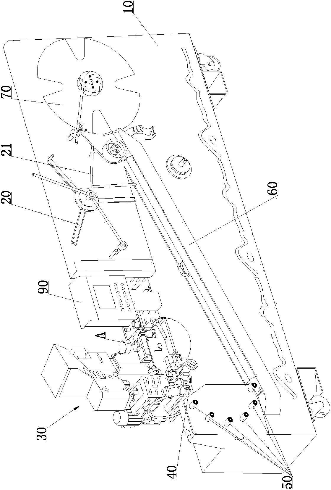
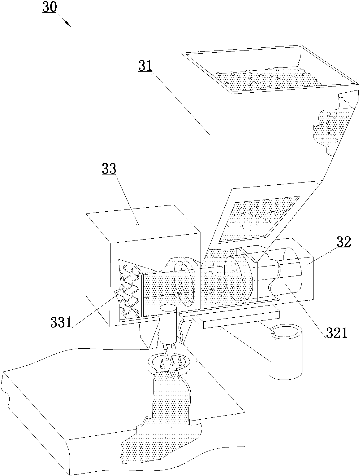
[0040] Such as Figure 1 to Figure 8 As shown, the edge strip glue applicator of the present invention includes a machine tool 10, and the machine tool 10 is provided with an unwinding reel 20, a glue melting device 30, a scraper coating device 40, an edge strip turning device, a cooling channel 60 and a winding Disc 70; Unwinding reel 20 is positioned above the front side of the machine tool 10, the glue melting device 30 is positioned at the rear side of the machine tool 10, the scraping device 40 is positioned at the front side of the machine tool 10 and is connected with the glue melting device 30, and the edge strip steering device is connected with the glue melting device 30. The output end of the squeegee coating device 40 is connected, that is, the edge banding after being glued by the squeegee coating device 40 will enter the edge banding turning device for bending and turning, and the cooling channel 60 is connected to the output end of the edge banding turning device...

Embodiment 2

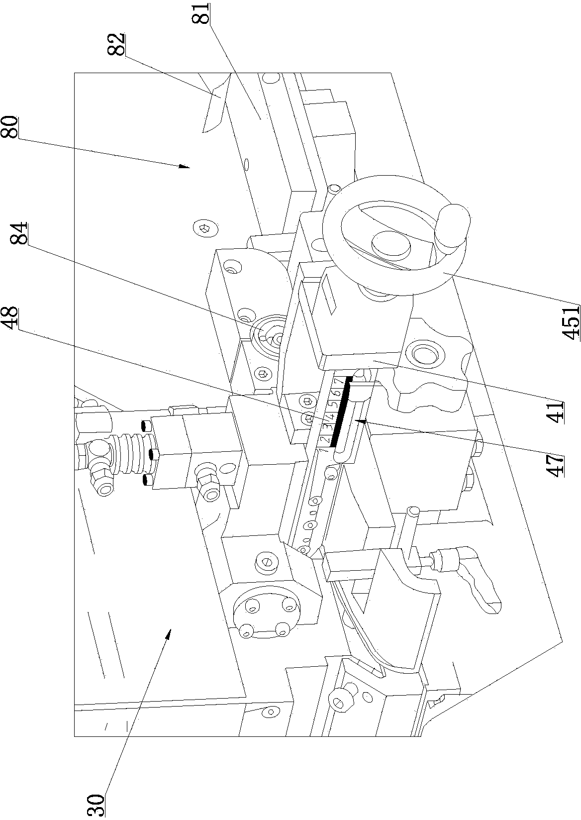
[0055] The difference between this embodiment and Embodiment 1 is that the shaft of the screw rod 45 is equipped with a scale indicator piece 46, and the side surface of the glue-coated positioning seat 41 is provided with an indicator piece moving groove 47, and the indicator piece moving groove 47 is provided with a moving groove 47. A scale line 48 is provided, and the scale indicator sheet 46 is positioned at the side of the scale display groove and points to the scale line 48, see Figure 4 with Figure 5 Specifically, when turning the hand wheel 451, the screw rod 45 drives the movable stopper 44 of the glue groove to move back and forth to adjust the glue width of the glue groove 43, wherein the value of the scale line 48 ranges from 10 to 70mm. When the rod 45 rotated, the scale indicating plate 46 installed on the shaft of the screw mandrel 45 moved with the screw mandrel 45, and the scale indicating plate 46 pointed to the corresponding scale line 48 values ​​in the ...

Embodiment 3

[0058] The difference between this embodiment and Embodiment 1 is that the machine tool 10 is also provided with a transfer device 80, the transfer device 80 is located between the unwinding reel 20 and the scraper coating device 40, the transfer device 80 includes a positioning conveyor 81, and the positioning One end of the conveying path 81 close to the unwinding reel 20 is provided with an edge banding strip compression shrapnel 82, and the end of the positioning conveying path 81 close to the scraping device 40 is provided with a conveying wheel 83 and a pressing wheel 84, and the conveying wheel 83 is positioned at the pressing Below the wheel 84, see figure 2 with Figure 7 ; Concretely, after the edge banding strip is discharged through the unwinding reel 20, it passes through the positioning conveyor 81 of the conveying device 80 arranged between the unwinding reel 20 and the scraping device 40, and the compression shrapnel provided by the positioning conveyor 81 fir...


PUM


Abstract

The invention relates to the technical field of edge banding production equipment, in particular to a scrape coating machine for an edge banding. The scrape coating machine comprises a machine tool provided with an unwinding plate, an adhesive melting device, a scrape coating device, an edge banding turning device, a cooling channel and a winding plate, wherein the unwinding plate is located above the front side of the machine tool, the adhesive melting device is located on the rear side of the machine tool, the scrape coating device is located on the front side of the machine tool and connected with the adhesive melting device, the edge banding turning device is connected with an output end of the scrape coating device, the cooling channel is connected with an output end of the edge banding turning device, and the winding plate is located on one side of an outlet end of the cooling channel. The scrape coating machine for the edge banding is small in size, lower in production cost and little in occupied space during use; the glue spreading edge sealing machine is suitable for coating the back side of the edge banding with a hot melt adhesive, is particularly suitable for the edge banding with the width ranging from 16 mm to 65 mm and the thickness ranging from 0.4 mm to 3 mm, the coating quantity is 50 -250 g / m<2>, the production efficiency is high, the adhesive coating is uniform and stable, and the adhesive coating quality is good.

Description

technical field [0001] The invention relates to the technical field of edge banding strip production equipment, in particular to an edge banding strip coating machine. Background technique [0002] Edge banding is a material for protecting, decorating and beautifying the section of furniture panels. Its main function is to seal the section of the panel so as to prevent the panel from being damaged by the environment and unfavorable factors during use. Unique color and texture design and other decorations make the applied furniture panel products more textured and three-dimensional. For flat edge banding products, back coating treatment is an important process related to product quality. [0003] The prior art has disclosed a device for applying hot melt adhesive on the back of the edge band, which includes an unwinding device for releasing the edge band, and applies hot melt adhesive on the back side of the edge band to obtain a glued edge band. A melt glue coating device,...

Claims


Application Information

Patent Timeline
IPC IPC(8): B05C5/04B05C11/04B05C11/10
Inventor 谢志昆刘志望沈利达吴峰
Owner DONGGUAN HUALI INDUSTRIES CO LTD
Why Eureka
Try Eureka