
Movable manual welding table for circuit board

A circuit board, movable technology, applied in printed circuits, welding equipment, auxiliary welding equipment, etc., can solve the problems of component displacement or falling, poor welding quality, easy to move, etc., to increase the utilization rate, Improve welding efficiency and improve aesthetics

Active Publication Date: 2014-12-24
SUZHOU VOCATIONAL UNIV
View PDF6 Cites 11 Cited by
  • Summary
  • Abstract
  • Description
  • Claims
  • Application Information

AI Technical Summary

Problems solved by technology

[0002] In the prior art, when manually soldering the components on the circuit board, usually the base material of the circuit board is placed flat on the welding workbench, and then the components to be soldered are manually selected from the component placement box, and placed The selected components are placed on the welding station, and then soldered with an electric soldering iron. This method is easy to move because the circuit board substrate is not fixed, which will cause the components to shift or fall, and the welding efficiency is low. Heat dissipation Poor performance and poor welding quality. For this reason, we have developed a manual welding station for movable circuit boards that can prevent components from falling during welding, has high welding efficiency, high welding quality, good heat dissipation, and good versatility.

Method used


Image

  • Movable manual welding table for circuit board
  • Movable manual welding table for circuit board
  • Movable manual welding table for circuit board

Examples


Embodiment Construction

[0027] The present invention will be further described in detail below in conjunction with the accompanying drawings and specific embodiments.

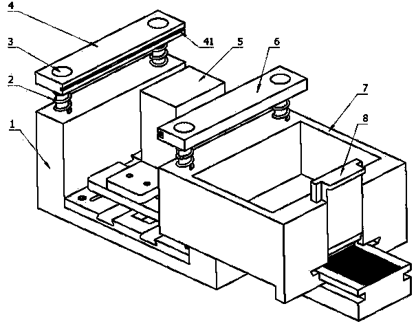
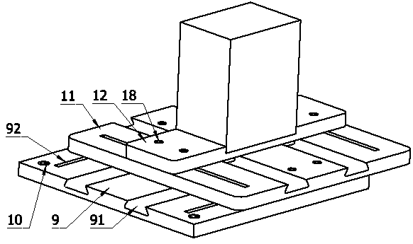
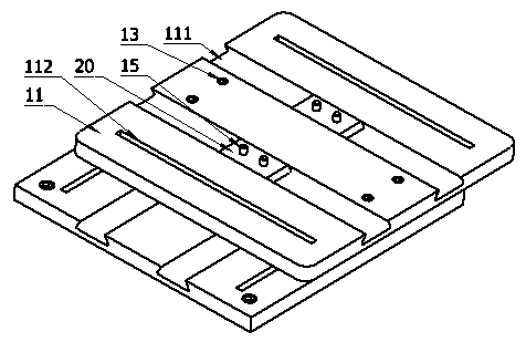
[0028] attached Figure 1-8It is a movable circuit board manual welding station according to the present invention, which includes a base guide rail, a cross slide module, and a movable clamp body module; one end of the base guide rail 1 is provided with a rectangular boss, and the other end of the base guide rail 1 is provided with a I-shaped guide rail 104; said rectangular boss is provided with two threaded holes 101 arranged at intervals, and each threaded hole 101 is provided with a guide rod 3; each guide rod 3 is sleeved with a large spring 2; The threaded end of the guide rod 3 passes through the stepped hole on the upper surface of the jaw 4 and is threadedly connected with the threaded hole 101, and the other end of the guide rod 3 is provided with a circular boss, and the circular boss can be Placed in the large hole of th...


PUM


Abstract

The invention discloses a movable manual welding table for a circuit board. The movable manual welding table for the circuit board comprises a base guide rail, a cross-shaped sliding plate module and a moving vice body module, wherein one end of the base guide rail is provided with a rectangular boss; the other end of the base guide rail is provided with an I-shaped guide rail; the upper part of the rectangular boss is provided with a jaw; a groove is formed in the inner side face of the jaw, and is used for installing one end of the circuit board; the moving vice body module comprises a moving vice body; the moving vice body can move along the I-shaped guide rail; the upper part of the moving vice body is provided with an elastic jaw; a T-shaped groove is formed in the inner side face of the elastic jaw, and is used for installing the other end of the circuit board; the cross-shaped sliding plate module is arranged between the rectangular boss and the I-shaped guide rail; the upper surface of the cross-shaped sliding plate module is provided with a support table; the support table can move front and back and left and right along with the cross-shaped sliding plate module. The movable manual welding table disclosed by the invention is capable of preventing devices from falling down during welding, and is good in welding efficiency, high in welding quality, good in heat dissipation performance and good in universality.

Description

technical field [0001] The invention relates to a movable circuit board manual welding station which can prevent components from falling during welding, has high welding efficiency, high welding quality, good heat dissipation and good versatility. Background technique [0002] In the prior art, when manually soldering the components on the circuit board, usually the base material of the circuit board is placed flat on the welding workbench, and then the components to be soldered are manually selected from the component placement box, and placed The selected components are placed on the welding station, and then soldered with an electric soldering iron. This method is easy to move because the circuit board substrate is not fixed, which will cause the components to shift or fall, and the welding efficiency is low. Heat dissipation Poor performance and poor welding quality, for this reason, we have developed a movable circuit board manual soldering station that can prevent comp...

Claims


Application Information

Patent Timeline
Patent Type & Authority Applications(China)
IPC IPC(8): B23K3/08B23K37/04B23K101/36
CPCB23K3/08B23K37/0408B23K37/0461B23K2101/42
Inventor 夏祖祥赵兆伟江龙王峰
Owner SUZHOU VOCATIONAL UNIV
Learn More