Automatic manipulator

A manipulator and automatic technology, applied in manipulators, chucks, manufacturing tools, etc., can solve the problems of complex structure and achieve the effect of simple structure

Inactive Publication Date: 2014-12-24
TAICANG ZIWU ELECTRICAL
View PDF7 Cites 5 Cited by
  • Summary
  • Abstract
  • Description
  • Claims
  • Application Information

AI Technical Summary

Problems solved by technology

[0002] Manipulators, also known as automatic hands, can imitate certain movements and functions of human hands and arms, and are used for automatic operations of grasping, carrying objects or operating tools according to a fixed program device; it can replace the heavy labor of people to realize the mechanization and automation of production, and can operate in a harmful environment to protect personal safety, so it is widely used in machinery manufacturing, metallurgy, electronics, light industry and atomic energy and other departments; existing manipulators Generally, only the grabbing function is realized, while intelligent manipulators generally require multiple dimensions, and the structure is very complex

Method used


Image

  • Automatic manipulator

Examples


Embodiment Construction

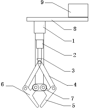
[0015] like figure 1 The shown automatic manipulator of the present invention includes a first hydraulic rod 1, a second hydraulic rod 2, a support arm 3, a connecting rod 4, a left clamp arm 5, a right clamp arm 6, a guide rail 8 and a control cabinet 9; A hydraulic rod 1 is fixed on the upper end of the support arm 3; the lower end of the support arm 3 is fixed with a second hydraulic rod 2; the front end of the hydraulic rod 2 is hinged to one end of the connecting rod 4; The right clamp arm 5; the middle part of the left clamp arm 6 and the right clamp arm 5 is hinged with the support arm 3; the tail of the first hydraulic rod 1 is movably connected to the guide rail 8; the control cabinet 9 is installed on the upper end of the guide rail 8; The control cabinet 9 is electrically connected to the first hydraulic rod 1 and the second hydraulic rod 2 .

[0016] Wherein, the middle parts of the left clamp arm 6 and the right clamp arm 5 are integrally made with a protruding p...


PUM


Abstract

The invention discloses an automatic manipulator comprising a first hydraulic lever, a second hydraulic lever, a support arm, connecting rods, a left clamp arm, a right clamp arm, a guide rail and a control cabinet. The first hydraulic lever is fixed at the upper end of the support arm; the second hydraulic lever is fixed at the lower end of the support arm; the front ends of the hydraulic levers are hinged with one ends of the connecting rods; the other ends of the connecting rods are hinged with the left clamp arm and the right clamp arm; the middle portion of each of the left clamp arm and the right clamp arm is hinged with the support arm, the tail portion of the first hydraulic lever is movably connected on the guide rail; the control cabinet is mounted at the upper end of the guide rail; the control cabinet is electrically connected with the first hydraulic lever and the second hydraulic lever. The automatic manipulator is simple in structure and capable of realizing horizontal and longitudinal adjustment; good handling effect can be achieved by the cooperation of the first hydraulic lever, the second hydraulic lever and the guide rail.

Description

technical field [0001] The invention relates to an automatic manipulator. Background technique [0002] Manipulators are also known as automatic hands, which can imitate certain movement functions of human hands and arms, and are used to grab, carry objects or operate automatic operating devices according to a fixed program; it can replace human heavy labor to realize production mechanization and Automation, which can operate in harmful environments to protect personal safety, is widely used in machinery manufacturing, metallurgy, electronics, light industry and atomic energy and other departments; existing manipulators generally only achieve the grabbing function, while intelligent manipulators generally require more dimension, the structure is very complex. Contents of the invention [0003] (1) Technical problems to be solved [0004] The technical problem to be solved by the invention is to provide an automatic manipulator with simple structure and capable of horizo...

Claims


Application Information

Patent Timeline
Patent Type & Authority Applications(China)
IPC IPC(8): B25J15/08
Inventor 王李剑
Owner TAICANG ZIWU ELECTRICAL
Why Eureka
Try Eureka