
Method for manufacturing a screen structure and screen structure for screen printing

A technology of screen and screen printing, applied in the field of screen structure, which can solve the problems of theoretical ink application limit and achieve high stability

Active Publication Date: 2014-12-24
GALLUS FERD RUESCH
View PDF9 Cites 1 Cited by
  • Summary
  • Abstract
  • Description
  • Claims
  • Application Information

AI Technical Summary

Problems solved by technology

The disadvantage here is that the theoretical ink application quantity, which is determined by the fabric thickness and the percentage open area of ​​the screen structure, is very limited
Especially limited when printing lines with a small width but at the same time a large height (as is required, for example, in the manufacture of solar cells)

Method used


Image

  • Method for manufacturing a screen structure and screen structure for screen printing
  • Method for manufacturing a screen structure and screen structure for screen printing
  • Method for manufacturing a screen structure and screen structure for screen printing

Examples


Embodiment Construction

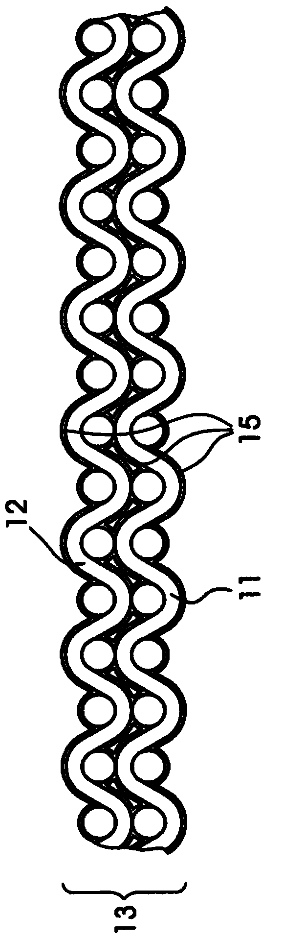
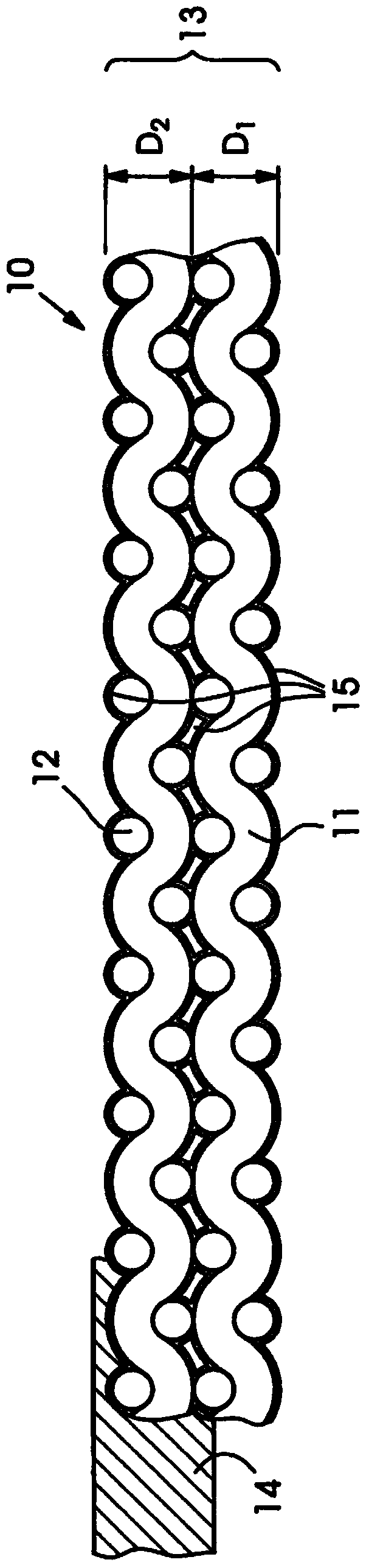
[0034] Figure 4 Shown is a flat screen material 10 according to the prior art with a textile layer 11 provided on one side with a photopolymer coating 14 (direct template). In an alternative embodiment not shown, an already patterned foil can be applied to the wire mesh structure 10 (indirect template). The nickel-plated flat screen material 10 is here formed in one piece from the fabric 11 . Different fabric forms are conceivable here, which are also referred to as fabric types.

[0035] This screen material 10 can be applied in rotary screen printing: in Figure 5 A screen 17 with a planar screen material 10 in the form of a cylindrical sleeve is shown in , which is used for rotary screen printing. The wire mesh material 10 here retains its cylindrical shape by end pieces, not shown in detail. Inside the screen 17 there is an invisible squeegee of the screen printing device in order to press the ink through the screen material. The orientation of the scraper may be par...


PUM


Abstract

A method for manufacturing a screen structure and a screen structure manufactured in accordance with the method which is used to manufacture the screen structure (10) including at least two mesh layers (11, 12). A first mesh layer (11) and a second mesh layer (12) are provided and brought together to contact each other. Advantageously, the first and second mesh layers (11, 12) are jointly metal-plated. The applied metal (15) firmly bonds the two mesh layers (11, 12)to each other to create a composite mesh (13). An advantage of the screen structure is that it has a particularly great ink application volume and a very high degree of stability.

Description

technical field [0001] The invention relates to a method for producing a wire mesh structure with the features of claim 1 or 8 and a wire mesh structure with the features of the preamble of claim 5 or 10 . Background technique [0002] Industrial applications of wire meshes and fabrics are disclosed by different specialized fields. In applications in the field of filtration, a square mesh shape is a common embodiment. The mesh shape has been transferred to printing applications. With the available photosensitive layers and the known application methods, a suitable image resolution can only be achieved with a large number of "supports". Fabrics with high mesh counts are therefore increasingly being used. [0003] In electronic printing, the thinnest possible screens or fabrics with the thinnest possible threads are used to ensure good paste flow-through and to achieve extremely fine image motifs. [0004] High paste application and precise image resolution are required in...

Claims


Application Information

Patent Timeline
IPC IPC(8): B41C1/14B41F15/34B41N1/24D03D1/00D03D13/00
CPCB32B5/028B32B5/26B32B2255/02B32B2255/205B32B2262/0276B32B2307/734B32B2307/75B32B2457/00B41C1/14B41C1/142B41N1/24B41N1/247
Inventor H-R·弗里克H·布罗克R·格罗伊特曼
Owner GALLUS FERD RUESCH
Learn More