Tile clamping device of tile fixing machine

A clamping device and tile-laying technology, which is applied in the direction of construction and building construction, can solve the problems of low laying efficiency, high labor intensity, uneven tile gaps, etc., and achieve improved firmness and stability, high versatility, and reduced effect of space

Inactive Publication Date: 2014-12-24
台州八鑫工贸股份有限公司
View PDF6 Cites 4 Cited by
  • Summary
  • Abstract
  • Description
  • Claims
  • Application Information

AI Technical Summary

Problems solved by technology

At present, the main method of laying tiles in China is still manual laying, but there are many defects in manual laying, such as: uneven gaps between tiles, low laying efficiency, and high labor intensity

Method used


Image

  • Tile clamping device of tile fixing machine
  • Tile clamping device of tile fixing machine
  • Tile clamping device of tile fixing machine

Examples


Embodiment 1

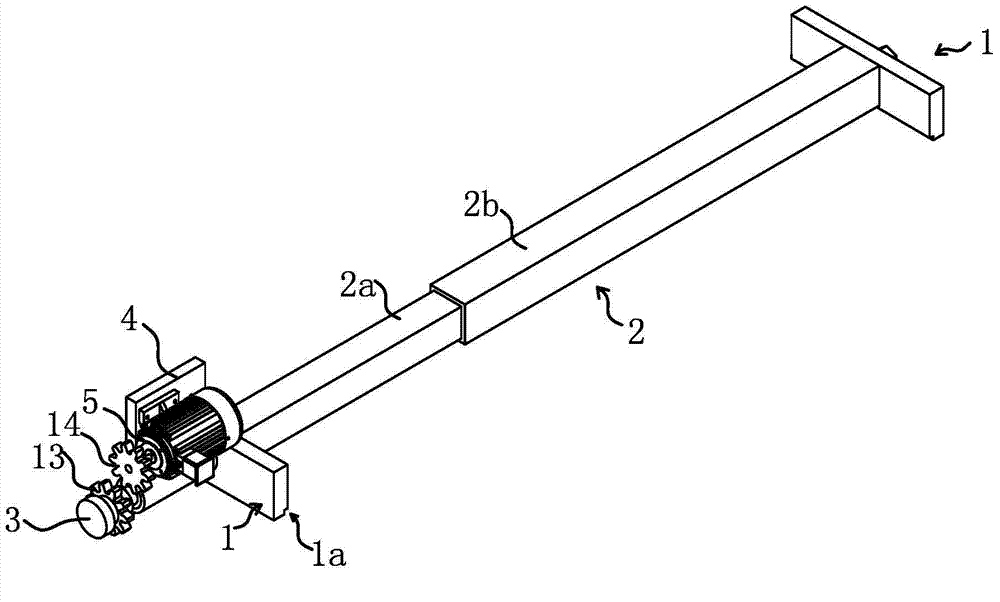
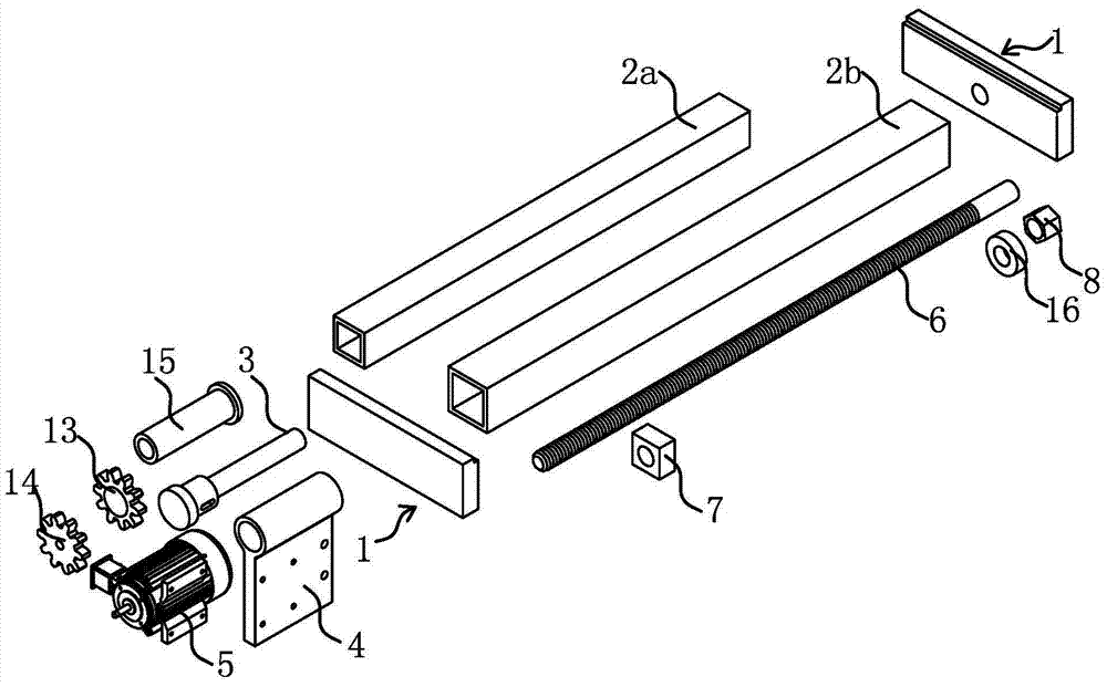
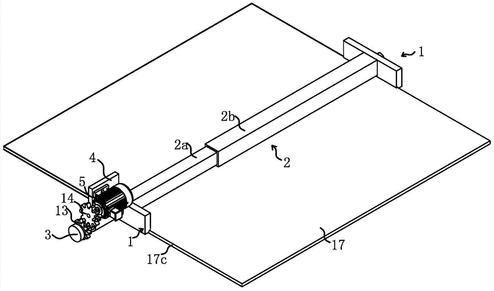
[0041] Such as Figure 1 to Figure 7 As shown, a tile clamping device of a tile tiling machine includes two strip-shaped clamping plates 1, and the two clamping plates 1 are arranged in parallel. Between the two clamping plates 1, there is a support rod 2 that can be stretched in a straight line. One end of the support rod 2 is fixedly connected to the surface of one clamping plate 1, and the other end of the support rod 2 is connected to the plate of another clamping plate 1. The surface is fixedly connected, and the two clamping plates 1 are connected through the support rod 2. In addition, the support rod 2 is provided with a locking mechanism capable of locking the length of the support rod 2 . In order to smoothly realize the flipping of tiles 17, a mounting seat 4 is also installed. Mounting holes are provided on the seat 4 and the mounting seat 4 is fixed on the tiling machine by parts such as screws, so that the whole clamping device can be fixed on the tiling machin...

Embodiment 2

[0046] Such as Figure 8 As shown, the structure and principle of this embodiment are basically the same as that of Embodiment 1, the difference is that: there is a clamping convex tooth 1b on the clamping surface 1a1 of the clamping plate 1, and the clamping convex tooth 1b is along the clamping The board 1 is arranged longitudinally. Using the clamping protruding teeth 1b to clamp the tile 17 relative to the plane clamps not only effectively improves the firmness of the clamping, but also completely eliminates the cracking of the ridge line angle caused by the unevenness of the tile side 17c when the tile 17 is clamped by the plane. In this embodiment, the clamping protruding teeth 1b and the clamping plate 1 are integrally formed, which can ensure the reliability of clamping.

Embodiment 3

[0048] Such as Figure 9 , Figure 10 As shown, the structure and principle of this embodiment are basically the same as that of Embodiment 1 and Embodiment 2. The difference is that the clamping plate 1 includes a clamping seat 1c and a clamping strip 1d, and the clamping notch 1a and the clamping The protruding teeth 1b are located on the clamping bar 1d, the support rod 2 is fixedly connected to the clamping seat 1c, and the clamping bar 1d is fixedly connected to the clamping seat 1c through the bolt 1d2. The clamping bar 1d is detachable relative to the clamping seat 1c, so the clamping bar 1d can be replaced according to the actual situation, thereby ensuring the firmness of the clamping. The actual situation is that the clamping convex teeth 1b are worn out, and the object to be clamped is changed, such as changing the tile 17 into a marble plate. Moreover, there is also a bolt hole 1d1 on the above-mentioned clamping strip 1d, the bolt hole 1d1 is strip-shaped, and t...


PUM


Abstract

The invention provides a tile clamping device of a tile fixing machine, and belongs to the field of building decoration machines. The tile clamping device solves the problems that an existing tile clamping device of the tile fixing machine is large in occupied area and high in manufacturing cost. The clamping device of the improved structure comprises two clamping plates which are symmetrically arranged. Supporting rods are arranged between the two clamping plates. One end of each supporting rod is fixedly connected with one clamping plate, and the other end of each supporting rod is fixedly connected with the other clamping plate. The supporting rods can be stretched out and drawn back. Locking mechanisms which can lock the length of the supporting rods are arranged on the supporting rods. The tile clamping device of the improved structure is simple in structure, high in use reliability and quite suitable for popularization.

Description

technical field [0001] The invention belongs to the field of building decoration machinery, and relates to a tile tiling machine, in particular to a tile clamping device of the tile tiling machine. Background technique [0002] With the continuous acceleration of the pace of modernization, more and more occasions need to lay tiles. Therefore, how to lay tiles with high efficiency and high quality has become a topic of research value. At present, the main way of laying tiles in China is still manual laying, but there are many defects in manual laying, such as: uneven gaps between tiles, low laying efficiency, and high labor intensity. In particular, the large-size floor tiles favored by users are more difficult to lay by hand, and the per capita daily laying volume is low. Therefore, mechanical operations are urgently needed for floor and wall tile laying. In recent years, more and more ideas related to tile laying machines have appeared, in which the clamping device plays a...

Claims


Application Information

Patent Timeline
Patent Type & Authority Applications(China)
IPC IPC(8): E04F21/22
Inventor 林健明
Owner 台州八鑫工贸股份有限公司
Why Eureka
Try Eureka