Tile clamping device for tiling machine
A clamping device and tile tiling technology, which is applied in the direction of construction and building structure, can solve the problems of low laying efficiency, uneven gap between tiles, and high labor intensity, and achieves improved firmness and stability, high versatility, and operation. handy effect
- Summary
- Abstract
- Description
- Claims
- Application Information
AI Technical Summary
Problems solved by technology
Method used
Image
Examples
Embodiment 1
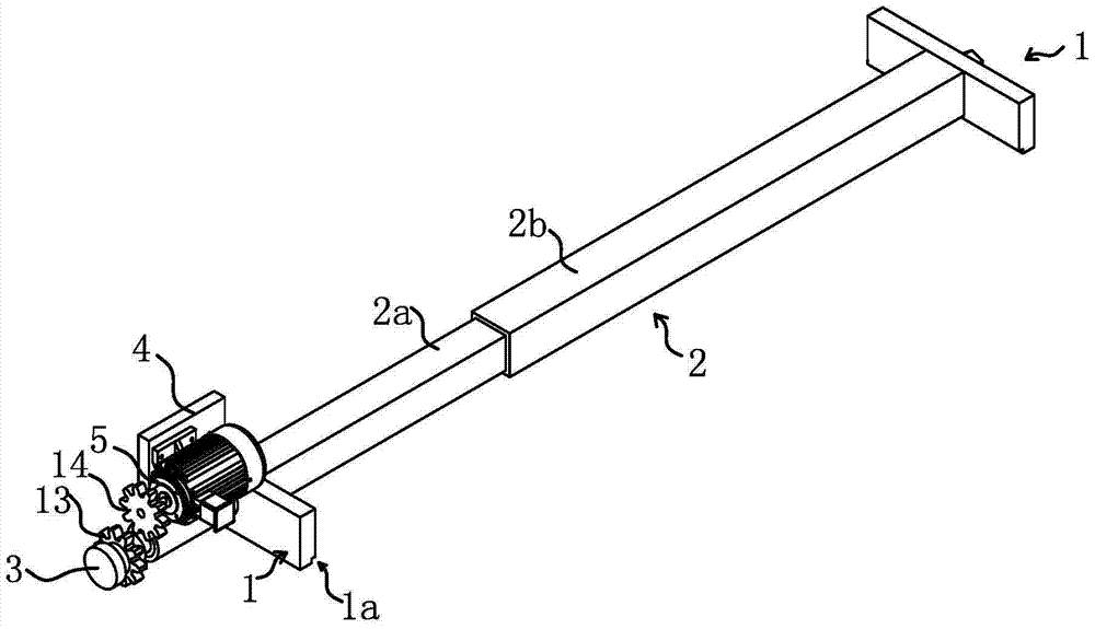
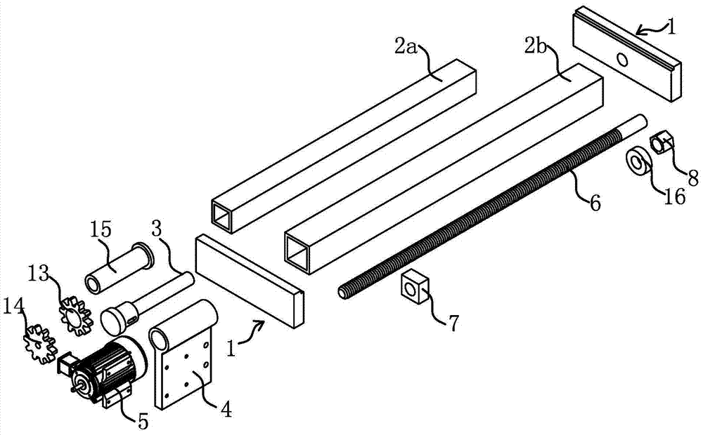
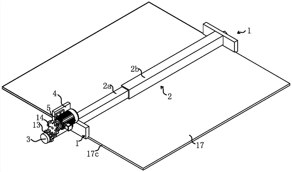
[0041] Such as Figure 1 to Figure 7 As shown, a ceramic tile clamping device of a tile applicator includes two strip-shaped clamping plates 1, and the two clamping plates 1 are arranged in parallel. A support rod 2 capable of linear expansion and contraction is arranged between the two clamping plates 1. One end of the support rod 2 is fixedly connected to the surface of a clamping plate 1, and the other end of the support rod 2 is connected to the plate of the other clamping plate 1. The surface is fixedly connected, and the two clamping plates 1 are connected through the supporting rod 2. In addition, a locking mechanism capable of locking the length of the support rod 2 is provided on the support rod 2. In order to smoothly realize the turnover of the tiles 17, a mounting seat 4 is also installed. The mounting seat 4 is located on the outside of the clamping plate 1. The tile clamping device of the tiler uses the mounting seat 4 as the basic part. Mounting holes are opene...
Embodiment 2
[0046] Such as Picture 8 As shown, the structure and principle of this embodiment are basically the same as that of the first embodiment. The difference lies in: the clamping surface 1a1 of the clamping plate 1 has a clamping convex tooth 1b, and the clamping convex tooth 1b is clamped along the clamping surface 1a1. The board 1 is arranged vertically. Using the clamping protruding teeth 1b to clamp the ceramic tile 17 relative to a flat surface not only effectively improves the firmness of the clamping, but also completely eliminates the phenomenon of uneven edge line corner cracking caused by the uneven side surface 17c of the ceramic tile when the flat surface clamps the ceramic tile 17. In this embodiment, the clamping protruding teeth 1b and the clamping plate 1 are integrally formed, which can ensure the reliability of clamping.
Embodiment 3
[0048] Such as Picture 9 , Picture 10 As shown, the structure and principle of this embodiment are basically the same as those of the first and second embodiments. The difference lies in: the clamping plate 1 includes a clamping seat 1c and a clamping bar 1d, a clamping recess 1a and a clamping The protruding teeth 1b are all located on the clamping bar 1d, the support rod 2 is fixedly connected to the clamping base 1c, and the clamping bar 1d and the clamping base 1c are fixedly connected by bolts 1d2. The clamping bar 1d is detachable from the clamping base 1c, so the clamping bar 1d can be replaced according to actual conditions, thereby ensuring the firmness of the clamping. The actual situation is that the clamping protruding teeth 1b are worn and the object to be clamped is changed, for example, the ceramic tile 17 is changed to a marble plate. In addition, the above-mentioned clamping strip 1d further has a bolt hole 1d1, the bolt hole 1d1 is strip-shaped, and the long...
PUM
 Abstract
Description
Claims
Application Information
 - R&D
- Intellectual Property
- Life Sciences
- Materials
- Tech Scout
- Unparalleled Data Quality
- Higher Quality Content
- 60% Fewer Hallucinations
Browse by: Latest US Patents, China's latest patents, Technical Efficacy Thesaurus, Application Domain, Technology Topic, Popular Technical Reports.
© 2025 PatSnap. All rights reserved.Legal|Privacy policy|Modern Slavery Act Transparency Statement|Sitemap|About US| Contact US: help@patsnap.com


