Oldham Sealed Couplings

A technology of cross sliders and couplings, which is applied in the direction of couplings, elastic couplings, engine seals, etc., and can solve the problems of reduced service life of the sealing device of the flap damper, impact on safety production and production environment, and wear and tear Parts cannot be compensated and other problems, to achieve the effect of ensuring pressure, improving service life, and simple structure

Active Publication Date: 2016-05-18
柔金(辽宁)电力科技发展有限公司
View PDF7 Cites 2 Cited by
  • Summary
  • Abstract
  • Description
  • Claims
  • Application Information

AI Technical Summary

Problems solved by technology

During use, the turning device needs to control the flow rate of the medium at any time. The function of the wind pressure is to spray the medium to the designated position. Since the bearing end cannot withstand the wind pressure, the medium penetrates into the sealing device through the through shaft, and the sealing device in the sealing device The medium wears the through shaft and sealing material in the middle for a long time, resulting in a gap between the sealing material and the through shaft. When the gap reaches the position of the sealing flange of the control device, due to the effect of dust wind pressure, the medium is directly sprayed to the outside of the equipment through the gap. Affects both safe production and the production environment
Moreover, the disadvantage of the existing equipment is that after the sealing device has been used for a period of time, because the worn part cannot be compensated, defects such as medium leakage and pressure loss occur, which greatly reduces the service life of the sealing device of the flap damper

Method used


Image

  • Oldham Sealed Couplings

Examples


Embodiment Construction

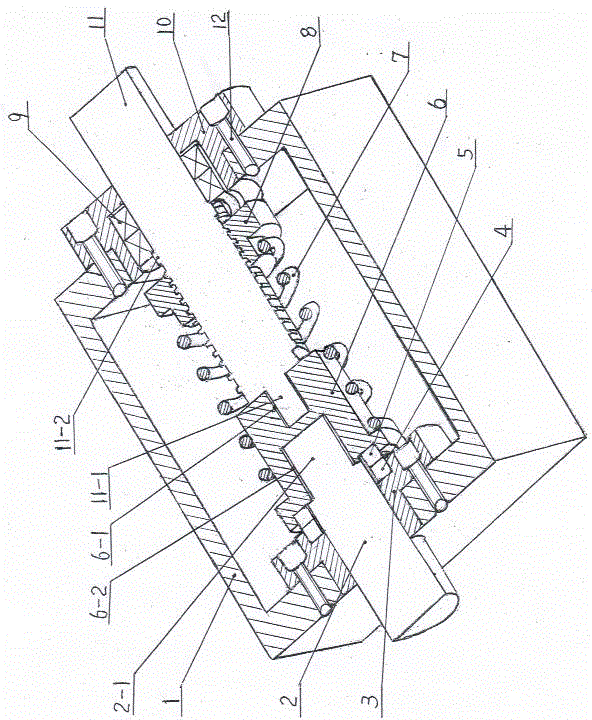
[0009] Examples, see attached figure 1 , the cross slider seal coupling is fixed with two connecting bolts 12 in the center hole of the left end of the housing 1, and the static sealing flange 3 is fixed, and the turning shaft 2 is movable in the static sealing flange 3, and the right end of the turning shaft 2 A flip shaft plug 2-1 is provided. In the center hole at the right end of the housing 1, a flange bearing seat 10 is fixed with two connecting bolts 12, and two sets of bearings 9 are arranged side by side in the flange bearing seat 10, and a swing rod is installed inside the flange bearing seat 10 and the bearing 9. The connecting shaft 11 is provided with a bearing limit boss 11-2 on the swing rod connecting shaft 11, and the bearing limit boss 11-2 is used for the axial limit of the bearing 9, and the swing rod connecting shaft 11 in the housing 1 Threaded connection is equipped with adjusting nut 8, and the left end of fork connecting shaft 11 is provided with fork...


PUM


Abstract

The invention belongs to the mechanical sealing devices, and in particular relates to a crosshead shoe sealing shaft coupler, wherein a static sealing flange (3) is fixedly arranged in the center hole in the left end of a shell (1) through a connecting bolt (12); an overturning shaft (2) is movably arranged in the static sealing flange (3) in a penetration manner; a flange bearing seat (10) is fixedly arranged in the center hole in the right end of the shell (1) through a connecting bolt (12); a swing rod connecting shaft (11) is arranged in the flange bearing seat (10) and a bearing (9) in the penetration manner; the overturning shaft (2) is connected with the swing rod connecting shaft (11) through a crosshead shaft coupling slider (6); the crosshead shaft coupling slider (6) is a stepped cylinder in shape; a static sealing ring (4) is arranged in the circular groove in the right end surface of the static sealing flange (3); a moving sealing ring (5) is arranged in the circular groove in the left end surface of the crosshead shaft coupling slider (6); the static sealing ring (4) and the moving sealing ring (5) both sleeve the overturning shaft (2). The crosshead shoe sealing shaft coupler has the advantages of simple structure and capabilities of purifying the production environment and prolonging the service life of equipment.

Description

technical field [0001] The invention belongs to a mechanical sealing device, in particular to an Oldham seal coupling. Background technique [0002] Over the years, the sealing of the flap damper of the dust and polluted gas conveying devices in the production industries such as electric power, building materials, and smelting has unsolvable disadvantages, which has caused hidden dangers to safe production and caused serious pollution to the production environment. The existing sealing device of the flap damper is generally an axial seal of a through shaft, and its structure is relatively simple, and a through shaft is used to connect the turning device, the control device and the sealing device. During use, the turning device needs to control the flow rate of the medium at any time. The function of the wind pressure is to spray the medium to the designated position. Since the bearing end cannot bear the wind pressure, the medium penetrates into the sealing device through th...

Claims


Application Information

Patent Timeline
Patent Type & Authority Patents(China)
IPC IPC(8): F16D3/26F16J15/16
Inventor 梁忠国段云龙李岩陈俊廷杨宇
Owner 柔金(辽宁)电力科技发展有限公司
Why Eureka
Try Eureka