Database disaster recovery system and database disaster recovery method

A database and quantity technology, applied in the database field, can solve the problems of poor data resource security performance, difficulty in migrating, backing up and responding to a variety of different business needs, and difficult to meet the diverse needs of enterprises, so as to achieve mutual backup and disaster recovery. Load sharing, easy to achieve effect

Active Publication Date: 2014-12-24
CEC CYBERSPACE GREAT WALL
View PDF7 Cites 11 Cited by
  • Summary
  • Abstract
  • Description
  • Claims
  • Application Information

AI Technical Summary

Problems solved by technology

[0002] Enterprises have various requirements for databases, especially for completely resource-isolated database products with different configurations, different capacities, and different functions. At present, it is difficult to deploy single-configuration database products to meet the diverse needs of enterprises.
[0003] The database products on the market are basically deployed in physical servers, which makes it difficult to migrate, back up and respond to various business needs; if the database is directly deployed on the virtual machine in the cloud computing environment, a simple database system will be formed The IO performance cannot meet the demand, and the security performance of data resources is relatively poor

Method used


Image

  • Database disaster recovery system and database disaster recovery method
  • Database disaster recovery system and database disaster recovery method

Examples


Embodiment 1

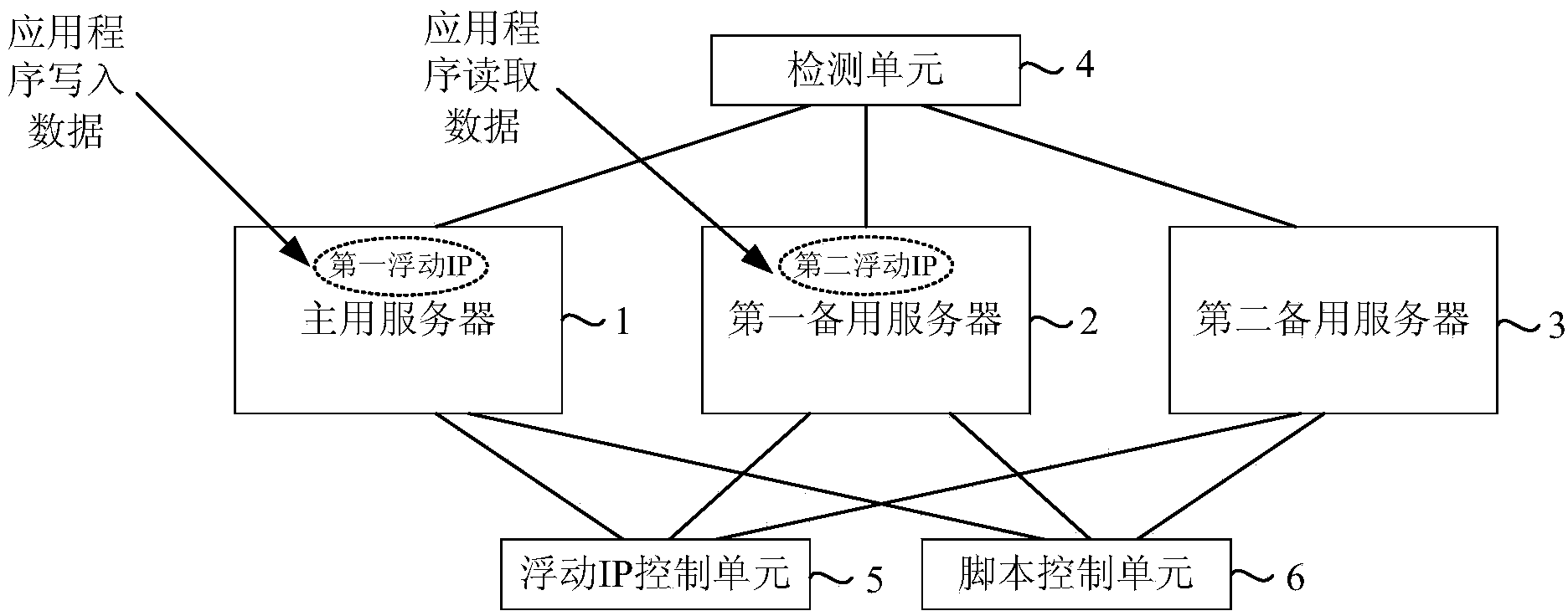
[0038] figure 1 A schematic structural diagram of a database disaster recovery system provided by Embodiment 1 of the present invention, as shown in figure 1 Shown: including: a primary server 1, a first backup server 2, at least one second backup server 3 ( figure 1 1), a detection unit 4, a floating IP control unit 5, and a script control unit 6 are shown in an example, wherein the primary server 1 is configured with a first floating IP, and the first backup server 2 is configured with a second floating IP. Unit 4 is used to detect whether the main server 1, the first backup server 2 and the second backup server 3 are abnormal; the floating IP control unit 5 is used to detect whether the main server 1, the first backup server 2 and the second backup server 3 When at least one of them is abnormal, control the first floating IP and / or the second floating IP to float to the target server; the script control unit 6 is used to control the target server to run the switching scrip...

Embodiment 2

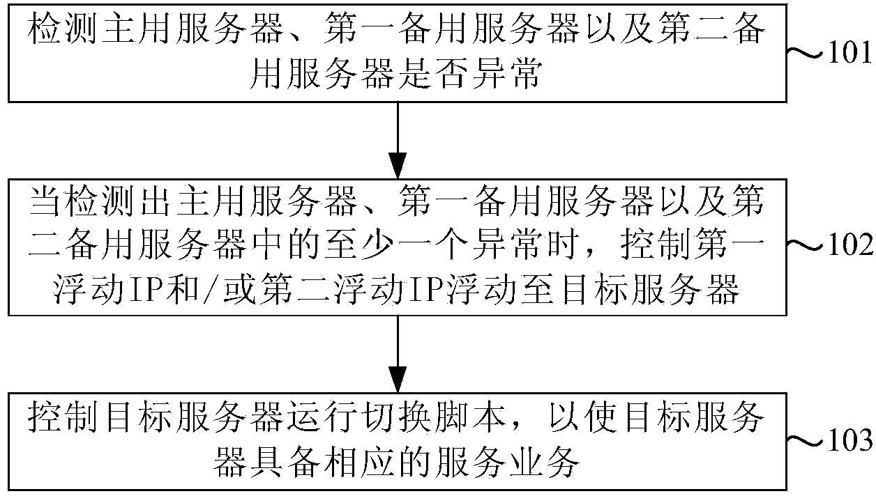
[0076] figure 2 It is a flowchart of a database disaster recovery method provided by Embodiment 2 of the present invention, such as figure 2 As shown, the database disaster recovery method is based on the database disaster recovery system, and the database disaster recovery system can adopt the database disaster recovery system provided in the first embodiment above. The database disaster recovery method includes:

[0077]Step 101: Detect whether the active server, the first backup server, and the second backup server are abnormal.

[0078] Step 101 can be performed by the detection unit in the first embodiment above, and for details, refer to the description in the first embodiment above.

[0079] When the database disaster recovery system is in an initial state, the active server is configured with a first floating IP, and the first standby server is configured with a second floating IP.

[0080] Step 102: when at least one of the active server, the first backup server a...


PUM


Abstract

The invention discloses a database disaster recovery system and a database disaster recovery method. The disaster recovery system comprises a main server, a first backup server, at least one second backup server, a detection unit, a floating IP control unit and a toggle script. According to the technical scheme, when the disaster recovery system stays at an initial state, the main server is configured with a first floating IP, the second backup server is configured with a second floating IP, the main server has a database writing business, and the first backup server has a data reading business, so that the load allocation of the disaster recovery system is realized; meanwhile, the detection unit detects whether the main server, the first backup server and the second backup server are abnormal or not, when at least one of the main server, the first backup server and the second backup server is abnormal, the floating IP control unit controls the first floating IP and / or the second floating IP to float to a target server, so that the active disaster recovery of the server can be realized, and the resource availability in the system can be maximally guaranteed.

Description

technical field [0001] The invention relates to the technical field of databases, in particular to a database disaster recovery system and a database disaster recovery method. Background technique [0002] Enterprises have various requirements for databases, especially for completely resource-isolated database products with different configurations, different capacities, and different functions. Currently, deploying single-configuration database products is difficult to meet the diverse needs of enterprises. [0003] The database products on the market are basically deployed in physical servers, which makes it difficult to migrate, back up and respond to various business needs; if the database is directly deployed on the virtual machine in the cloud computing environment, a simple database system will be formed The IO performance cannot meet the demand, and the security performance of data resources is relatively poor. Contents of the invention [0004] The invention prov...

Claims


Application Information

Patent Timeline
Patent Type & Authority Applications(China)
IPC IPC(8): G06F17/30G06F11/14H04L29/08
CPCG06F11/1464G06F16/90H04L67/12
Inventor 王贵宗
Owner CEC CYBERSPACE GREAT WALL
Why Eureka
Try Eureka