Organic lighting structure

A technology of light-emitting structure and organic light-emitting layer, applied in the direction of organic semiconductor devices, electrical components, circuits, etc., can solve the problem of low light-emitting efficiency of OLED light-emitting structure, and achieve the effect of improving light-emitting efficiency and high application value

Active Publication Date: 2014-12-24
EVERDISPLAY OPTRONICS (SHANGHAI) CO LTD
View PDF5 Cites 22 Cited by
  • Summary
  • Abstract
  • Description
  • Claims
  • Application Information

AI Technical Summary

Problems solved by technology

Some light is not emitted from the effective light-emitting area and direction,

Method used


Image

  • Organic lighting structure
  • Organic lighting structure
  • Organic lighting structure

Examples


Embodiment Construction

[0031] Example embodiments will now be described more fully with reference to the accompanying drawings. Example embodiments may, however, be embodied in many forms and should not be construed as limited to the embodiments set forth herein; rather, these embodiments are provided so that this disclosure will be thorough and complete, and will fully convey the concept of example embodiments to those skilled in the art. In the drawings, the thickness of regions and layers are exaggerated for clarity. The same reference numerals in the drawings denote the same or similar structures, and thus their detailed descriptions will be omitted.

[0032] Furthermore, the described features, structures, or characteristics may be combined in any suitable manner in one or more embodiments. In the following description, numerous specific details are provided in order to give a thorough understanding of embodiments of the present disclosure. However, one skilled in the art will appreciate tha...


PUM


Abstract

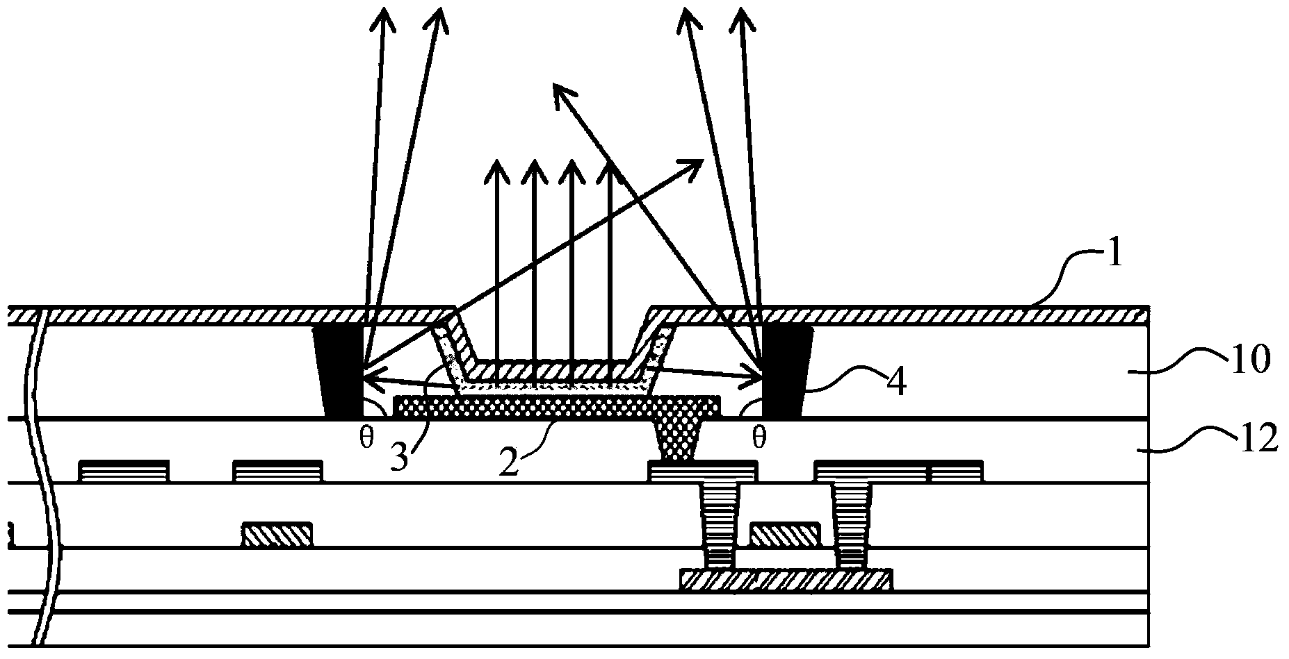
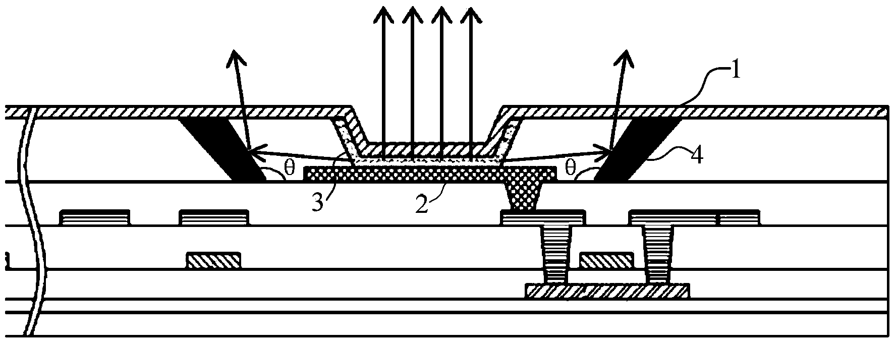
The invention discloses an organic lighting structure comprising an anode layer and a cathode layer, and an organic lighting layer arranged between the anode layer and the cathode layer; the organic lighting structure also comprises a side face reflection layer; the anode layer has a reflection layer, and the cathode layer is a transparent structure; the side face reflection layer is arranged under the cathode layer so as to form a light emitting zone with the anode layer; the anode layer and the side face reflection layer reflect the light emitted by the organic lighting layer, so the light can be emitted from the lighting emitting zone. The side face reflection layer is arranged around the organic lighting layer so as to reflect the light of side directions, thus improving light emitting efficiency of the organic lighting structure having very high application value.

Description

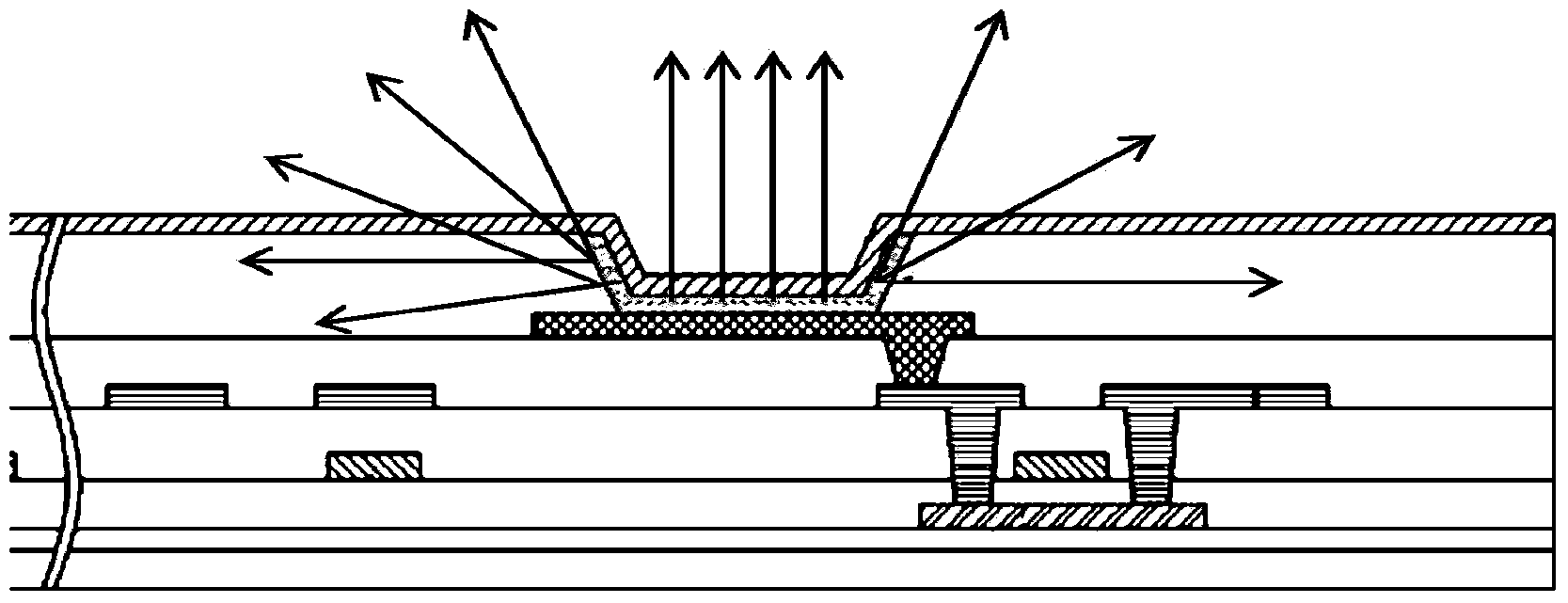
technical field [0001] The present invention relates to an OLED (Organic Light-Emitting Diode, organic light-emitting diode) structure. Background technique [0002] OLED is a self-luminous display technology. The luminous efficiency of OLED is related to the design of selected luminescent materials, backplane and peripheral components. OLEDs must be reflected by means of a reflective layer to increase luminous brightness, thereby improving related display performance. [0003] For the OLED light-emitting structure in the prior art, see figure 1 shown. The anode in the OLED light-emitting structure has a reflective layer for reflecting light generated by the organic light-emitting layer. The reflective layer can be an anode metal plane. The light generated by the OLED light-emitting structure is as follows figure 1 As shown, the light emitted by it is randomly scattered. Some light is not emitted from the effective light-emitting area and direction, resulting in low ov...

Claims


Application Information

Patent Timeline
IPC IPC(8): H01L51/50
CPCH10K59/122H10K50/818H10K50/856H10K2102/3026
Inventor 刘志鸿王承贤黄俊杰
Owner EVERDISPLAY OPTRONICS (SHANGHAI) CO LTD
Why Eureka
Try Eureka