
Fuel cell system and centrifugal water separator for fuel cell system

A fuel cell system and fuel cell stack technology, applied in the direction of fuel cells, fuel cell additives, separation methods, etc., can solve the problems of low humidity, reduced fuel cell performance and life, etc., and achieve the effect of easy manufacture and high efficiency

Active Publication Date: 2014-12-24
FORD GLOBAL TECH LLC
View PDF5 Cites 16 Cited by
  • Summary
  • Abstract
  • Description
  • Claims
  • Application Information

AI Technical Summary

Problems solved by technology

Additionally, the high efficiency of conventional separators can result in too low humidity and can reduce fuel cell performance and life as some humidity is expected in the recycle stream

Method used


Image

  • Fuel cell system and centrifugal water separator for fuel cell system
  • Fuel cell system and centrifugal water separator for fuel cell system
  • Fuel cell system and centrifugal water separator for fuel cell system

Examples


Embodiment Construction

[0022] As required, specific embodiments of the present invention are disclosed herein; however, it is to be understood that the disclosed embodiments are merely exemplary of the invention, which may be embodied in various and alternative forms. The figures are not necessarily to scale; some features may be exaggerated or minimized to show details of particular components. Therefore, specific structural and functional details disclosed herein are not to be interpreted as limiting, but merely as a representative basis for teaching one skilled in the art to variously employ the present invention. Descriptions of ingredients in chemical terms refer to the ingredients when added to any of the compounds specified in the specification and do not necessarily exclude chemical interactions between the ingredients of the mixture formed when mixed.

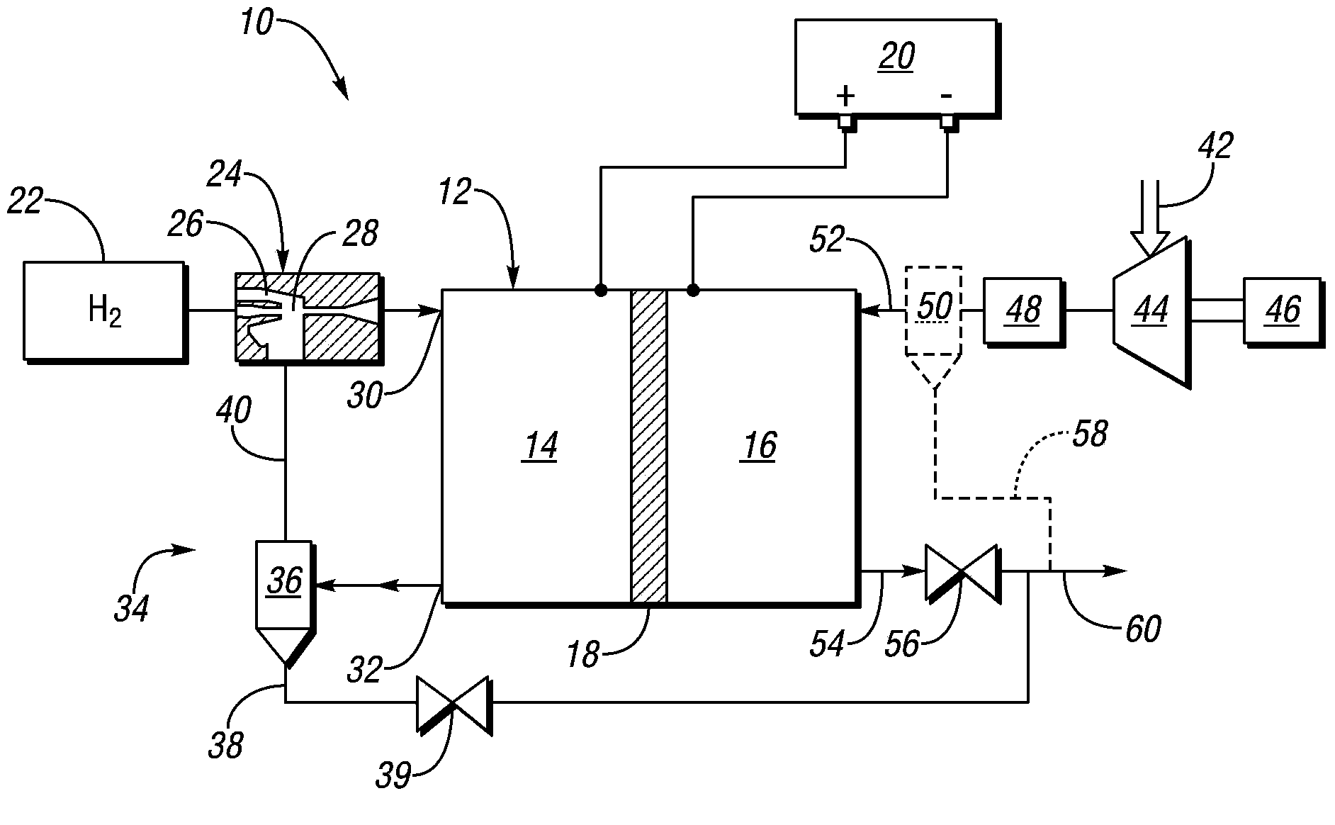
[0023] figure 1 A fuel cell system 10 according to at least one embodiment is schematically shown in the form of a process flow diagram. ...


PUM


Abstract

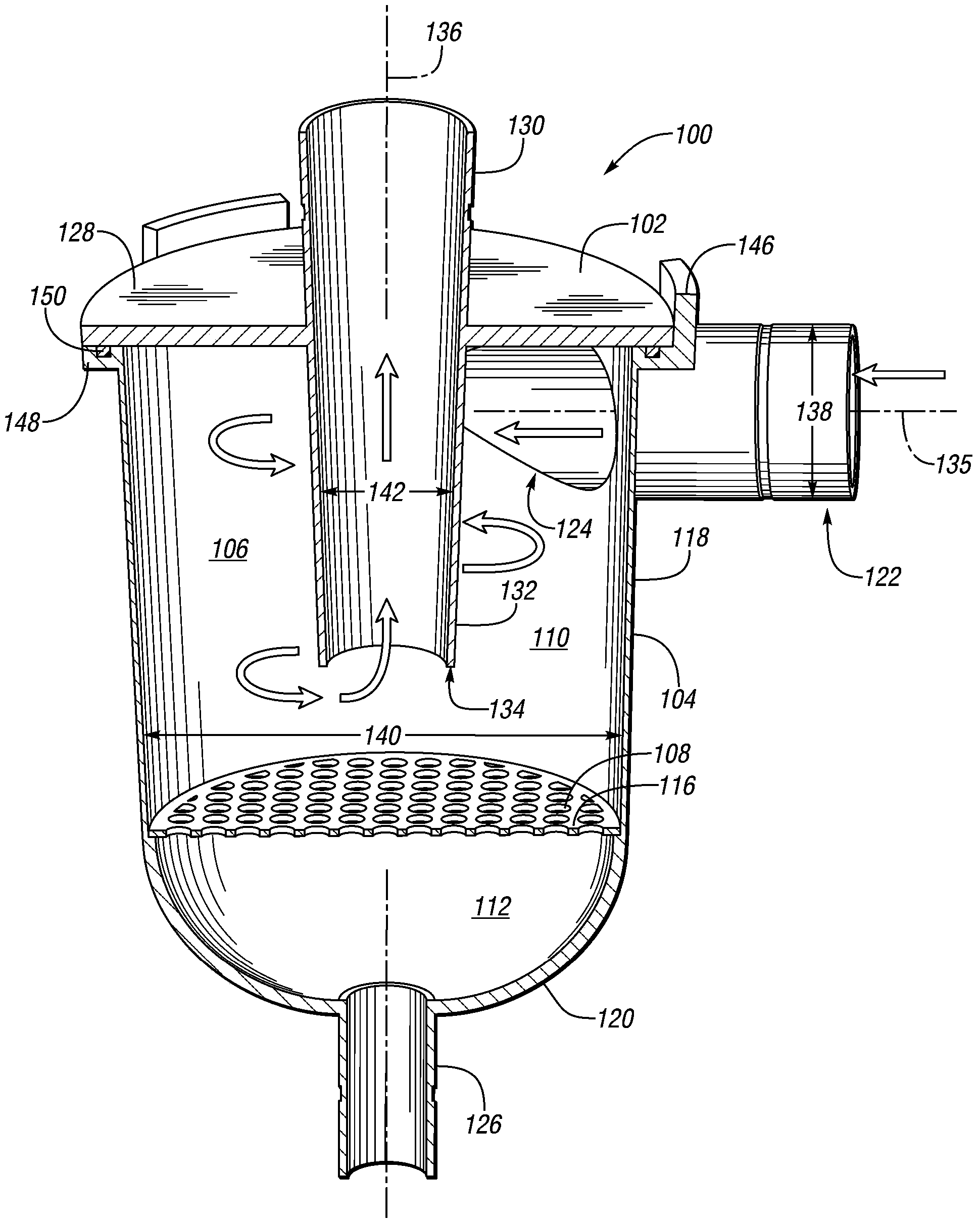
The invention provides a fuel cell system and a centrifugal water separator for the fuel cell system. The fuel cell system includes a fuel cell stack in fluid communication with a separator. The separator has a first portion and a second portion forming a chamber. The first portion has a continuous inner wall and an end wall, with an inlet conduit connected to the inner wall and a liquid drain connected to the end wall. The second portion has an end wall and an outlet conduit extending into the chamber to form a channel with the inner wall of the first portion. A fuel cell separator includes a first end and a second end connected by a side wall to define a separation chamber. An inlet conduit is tangentially connected to the wall. An outlet conduit is connected to the first end and extending into the chamber to form a channel with the wall. A liquid drain is connected to the second end.

Description

technical field [0001] Embodiments relate to an apparatus for removing water from a fuel cell system. Background technique [0002] During fuel cell operation, by-products such as product water and nitrogen, as well as undepleted hydrogen, may form on the anode side of the fuel cell stack. In some known systems, the accumulation of product water, as well as the accumulation of nitrogen, is controlled in an attempt to avoid degrading the performance of the fuel cell and / or avoiding shutdown of the fuel cell system. One known method is to release water and nitrogen through channels downstream of the fuel cell stack. The by-products can be recycled so that undepleted hydrogen is returned to the anode side of the fuel cell stack. Additionally, recirculation can be used to humidify the anode side to facilitate efficient chemical conversion and extend the life of the battery membrane. However, liquid water, such as droplets, may need to be removed from the recirculation flow to...

Claims


Application Information

Patent Timeline
IPC IPC(8): H01M8/04
CPCB01D45/12H01M8/04097H01M8/04126H01M8/04164B01D53/26B01D53/265B01D2256/16Y02E60/50
Inventor 克雷格·温菲尔德·彼得森斯蒂芬·波特文威廉· F·桑得逊
Owner FORD GLOBAL TECH LLC
Learn More