Engineering site waste residue cleaning and crushing device

A technology for engineering sites and crushing devices, which is applied in grain processing, dispersed particle separation, mechanically driven excavators/dredgers, etc. Avoid dust flying, protect health, simple and convenient operation

Active Publication Date: 2019-09-10
田宏照
View PDF8 Cites 2 Cited by
  • Summary
  • Abstract
  • Description
  • Claims
  • Application Information

AI Technical Summary

Problems solved by technology

These materials are of no help to the building itself, but they are substances produced during the construction process, which need to be treated accordingly, so that the ideal project construction can be achieved, because it is an overall process, such as Without treatment, it will also cause damage to the environment, so it is also very important to consider the link of crushing and recycling
In today's rapid development, the continuous renewal of buildings has led to a sharp increase in the amount of construction waste. However, when the residues of the existing engineering sites are cleaned and treated, a large amount of dust is often generated, which seriously affects the working environment of engineering personnel and even affects the health of workers. In good health, and the existing cleaning and crushing devices require manual handling for slag loading and slag dumping, which is extremely labor-intensive

Method used


Image

  • Engineering site waste residue cleaning and crushing device
  • Engineering site waste residue cleaning and crushing device
  • Engineering site waste residue cleaning and crushing device

Examples


Embodiment Construction

[0025] The following will clearly and completely describe the technical solutions in the embodiments of the present invention with reference to the accompanying drawings in the embodiments of the present invention. Obviously, the described embodiments are only some, not all, embodiments of the present invention.

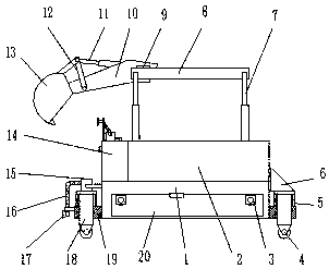
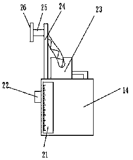
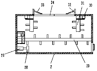
[0026] refer to Figure 1-5 A waste slag cleaning and crushing device for an engineering site, comprising a slag collecting box 1, support seats 19 are welded to the bottom of the outer walls on both sides of the slag collecting box 1, and a water tank 14 is fixed on one side of the top outer wall of the slag collecting box 1 by screws. The other side of the top outer wall of the slag box 1 is fixed with a crushing box 2 by screws, and the four corners of the top outer wall of the crushing box 2 are fixed with a first hydraulic cylinder 7 by screws, and the outer walls of one side of every two first hydraulic cylinders 7 are fixed by screws. The same support plate 8 ...


PUM


Abstract

The invention belongs to the technical field of engineering site cleaning, and particularly relates to an engineering site waste residue cleaning and crushing device. Aiming at the problems that according to the design of a waste residue cleaning and crushing device, the environment is polluted, the operation difficulty is large, and the manpower and the financial resources are wasted, a scheme isprovided. According to the scheme, the device comprises a residue collecting box, supporting bases are welded to the bottoms of the outer walls at the two sides of the residue collecting box, a watertank is fixed on one side of the outer wall of the top of the residue collecting box through screws, the other side of the outer wall of the top of the residue collecting box is fixedly provided witha crushing box through screws, first hydraulic cylinders are fixed at the four corners of the outer wall of the top of the crushing box through screws, one outer walls of one sides of every two firsthydraulic cylinders are fixedly provided with same supporting plates through screws, and electric control sliding rails are fixed on the outer walls of one sides of the supporting plates through screws. According to the device, the phenomenon of side slipping is avoided, the waste residue digging difficulty can be reduced, the working efficiency is improved, the cleaning and crushing cost is reduced, the body health of workers is protected, the environmental protection effect is improved, and meanwhile, the cost is saved.

Description

technical field [0001] The invention relates to the technical field of engineering site cleaning, in particular to a waste slag cleaning and crushing device for an engineering site. Background technique [0002] Abandoned stone bricks on the construction site are a kind of construction waste, and construction waste refers to construction waste generated in engineering due to human or natural reasons. These materials are of no help to the building itself, but they are substances produced during the construction process, which need to be treated accordingly, so that the ideal project construction can be achieved, because it is an overall process, such as If it is not treated, it will also cause damage to the environment, so it is also very important to consider the link of crushing and recycling. In today's rapid development, the continuous renewal of buildings has led to a sharp increase in the amount of construction waste, but the existing engineering site residues often ge...

Claims


Application Information

Patent Timeline
Patent Type & Authority Applications(China)
IPC IPC(8): B02C21/02E02F3/28B01D47/06
CPCB01D47/06B02C21/02E02F3/28
Inventor 田宏照
Owner 田宏照
Why Eureka
Try Eureka