Microstrip filter with controllable transmission zeros

A microstrip filter and transmission zero technology, which is applied to waveguide-type devices, electrical components, circuits, etc., can solve the problems of difficult position control, small number of zeros, sensitive coupling of resonators, etc., and achieves convenient processing and frequency selectivity. Improved, low-cost effects

Active Publication Date: 2014-12-24
UNIV OF ELECTRONIC SCI & TECH OF CHINA
View PDF2 Cites 9 Cited by
  • Summary
  • Abstract
  • Description
  • Claims
  • Application Information

AI Technical Summary

Problems solved by technology

[0004] The purpose of the present invention is to propose a microstrip filter with controllable transmission zeros, which overcomes the di

Method used


Image

  • Microstrip filter with controllable transmission zeros
  • Microstrip filter with controllable transmission zeros

Examples


Embodiment Construction

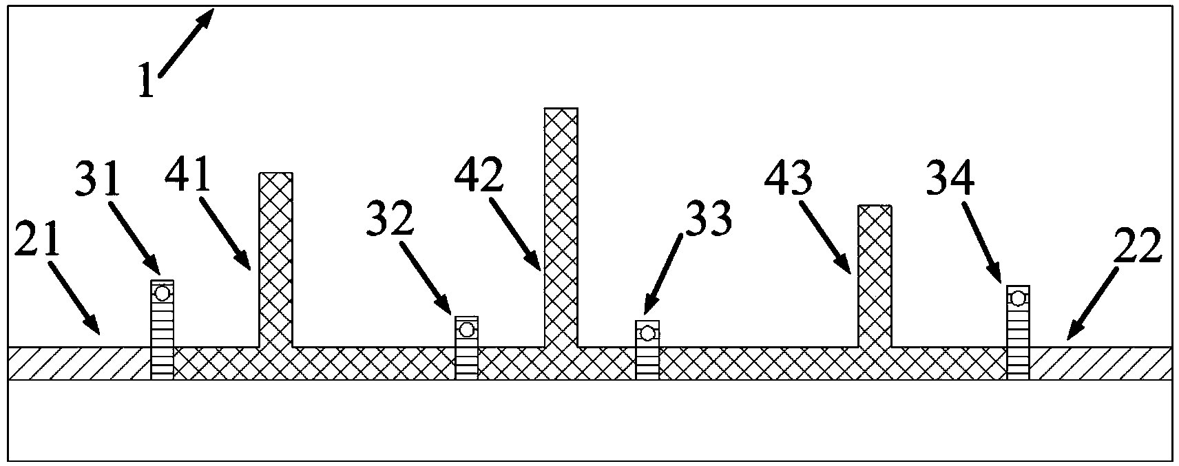
[0011] The present invention will be further described below in conjunction with accompanying drawing and specific embodiment: figure 1 As shown, a microstrip filter with controllable transmission zero point, the lower surface of the dielectric substrate 1 is completely covered by a metal layer, and the metal layer on the upper surface includes the first and second input and output feeders 21, 22, the first, The second, third, and fourth short-circuit stubs 31, 32, 33, and 34; the first, second, and third resonators 41, 42, and 43; the first input-output feeder 21, the first short-circuit stub 31, and the first resonance 41, the second short-circuit branch 32, the second resonator 42, the third short-circuit branch 33, the third resonator 43, the fourth short-circuit branch 34, and the second input-output feeder 22 are connected in sequence, and the first and fourth short-circuit branches 31 and 34 are perpendicular to the first and second input and output feeders 21 and 22 re...


PUM


Abstract

The invention discloses a microstrip filter with controllable transmission zeros. The lower surface of a dielectric substrate (1) of the microstrip filter is completely covered with a metal layer, and a first input and output feeder (21), a first short-circuit stub (31), a first resonator (41), a second short-circuit stub (32), a second resonator (42), a third short-circuit stub (33), a third resonator (43), a fourth short-circuit stub (34) and a second input and output feeder (22) of a metal layer of the upper surface of the dielectric substrate (1) are connected in sequence. The first resonator (41), the second resonator (42) and the third resonator (43) are formed by connecting three inverted-T-shaped microstrip lines, each resonator can generate one transmission zero, and the positions of the transmission zeros can be controlled according to the lengths of open-circuit stubs on the resonators. The microstrip filter has the advantages of being convenient to process and low in cost and weight; meanwhile, the number of the transmission zeros is large, the out-of-band rejection performance and frequency selectivity of the microstrip filter are improved, and the microstrip filter can be widely applied to wireless communication systems.

Description

technical field [0001] The invention relates to a microstrip filter with controllable transmission zero point, which belongs to the technical field of microwave passive devices. Background technique [0002] Filter is a key device in radio technology, its role is to filter out unwanted frequency components, and it is widely used in various commercial and military fields, such as radar systems, wireless communication systems, and medical imaging systems. In recent years, various wireless communication systems have developed rapidly, such as wireless local area network, mobile communication, and global positioning system, and there is certain interference in the frequency spectrum between the systems. Therefore, more and more stringent index requirements are put forward for microwave filters. For example, the filter in the microwave integrated circuit needs to be miniaturized, which can reduce the size of the system and save cost; the mobile communication base station require...

Claims


Application Information

Patent Timeline
IPC IPC(8): H01P1/203
Inventor 林先其程飞江源聂丽英张瑾于家伟宋开军樊勇
Owner UNIV OF ELECTRONIC SCI & TECH OF CHINA
Why Eureka
Try Eureka