
Sliding window-based estimation compensation method for CO-OFDM optical phase noise

A CO-OFDM and sliding window technology, which is applied in the field of CO-OFDM optical phase noise estimation and compensation based on sliding windows, can solve the problems of limiting the overall performance of the CO-OFDM system, reducing the effective rate and spectrum utilization of the system, and increasing the pilot frequency Quantity and other issues

Active Publication Date: 2014-12-24
SOUTH CHINA NORMAL UNIVERSITY
View PDF3 Cites 5 Cited by
  • Summary
  • Abstract
  • Description
  • Claims
  • Application Information

AI Technical Summary

Problems solved by technology

In order to achieve the set performance index, this method needs to increase the number of pilots, thereby reducing the effective rate and spectrum utilization of the system;
[0006] (2) In the case of large optical phase noise, the estimation error of the phase noise estimation scheme of a single CO-OFDM symbol is large, which seriously limits the overall performance of the CO-OFDM system

Method used


Image

  • Sliding window-based estimation compensation method for CO-OFDM optical phase noise
  • Sliding window-based estimation compensation method for CO-OFDM optical phase noise
  • Sliding window-based estimation compensation method for CO-OFDM optical phase noise

Examples


Embodiment 1

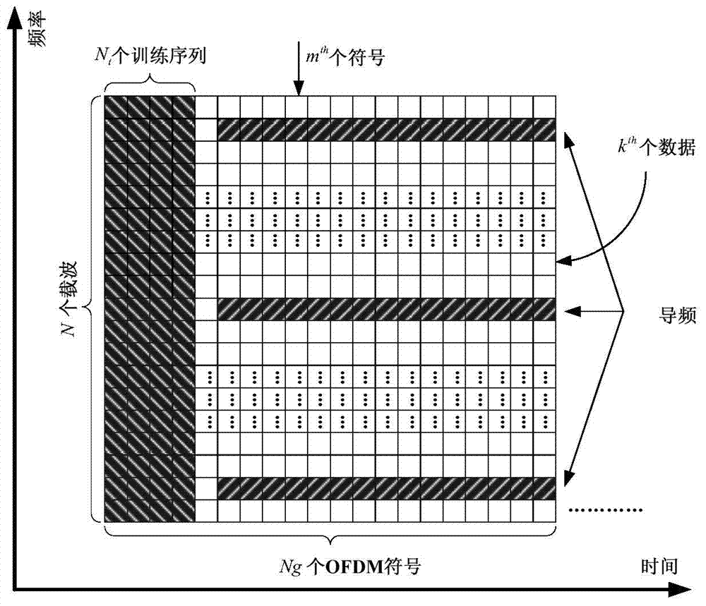
[0048] The method of the invention mainly relates to the problem of signal processing at the receiving end of a coherent optical orthogonal frequency division multiplexing system (CO-OFDM). In this embodiment, the pilot frequency is used in the CO-OFDM receiver module to estimate the common phase noise of each CO-OFDM symbol, so the signal data frame structure at the CO-OFDM transmitter is as follows image 3 shown.

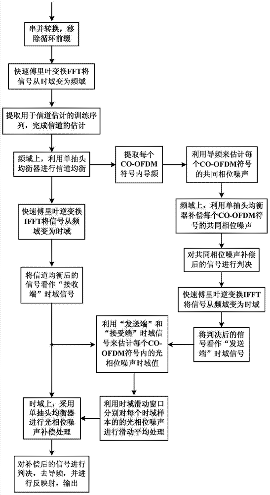
[0049] Combine below figure 1 and figure 2 , the steps of a method for estimating and compensating CO-OFDM optical phase noise based on a sliding window in this embodiment are described in detail.

[0050] S101: The receiving end performs serial-to-parallel conversion on the received signal.

[0051] S102: Remove the cyclic prefix.

[0052] S103: Transform the time-domain signal into a frequency-domain signal by using Fast Fourier Transform (FFT).

[0053] S104: Extract a training sequence used for channel estimation, and complete channel estimation.

[00...


PUM


Abstract

The invention discloses a sliding window-based estimation compensation method for a CO-OFDM optical phase noise. The method comprises the following steps of: estimating the common phase noise of each CO-OFDM symbol and completing compensation in a frequency domain, then judging, and carrying out IFFT transform on the judged signal to obtain a hypothetical 'transmitting end' time-domain signal; estimating an optical phase noise time-domain value in each CO-OFDM symbol by virtue of the hypothetical 'transmitting end' time-domain signal and a 'receiving end' time-domain signal polluted by an optical phase noise, then carrying out moving average processing on the optical phase noise of each time-domain sample, finally carrying out optical phase noise compensation processing on each CO-OFDM symbol in time domain. The method is capable of tracking the change conditions of the optical phase noises, and improving the accuracy of optical phase noise estimation and the performance of the whole optical communication system, high in practicability, and capable of effectively lowering the requirements of a CO-OFDM system on the line width of a laser light source, as well as has important significance in applications in the next generation of high-speed optical communication networks.

Description

technical field [0001] The invention relates to the technical field of optical communication, in particular to a method for estimating and compensating CO-OFDM optical phase noise based on a sliding window. Background technique [0002] Coherent Optical Orthogonal Frequency Division Multiplexing (CO-OFDM), as a multi-carrier coherent optical communication technology, has attracted extensive attention of scholars in recent years. Compared with single-carrier coherent optical communication technology, CO-OFDM can achieve higher spectral efficiency, more flexible spectrum usage, more efficient channel equalization and higher spectrum scalability. Although the CO-OFDM technology has many advantages mentioned above, there are still some technical challenges in its application in the optical fiber communication system. Among them, a major defect of the CO-OFDM system is that it is extremely sensitive to optical phase noise. [0003] In order to suppress the influence of optical ...

Claims


Application Information

Patent Timeline
Patent Type & Authority Applications(China)
IPC IPC(8): H04L27/26H04L25/02H04L25/03
Inventor 洪学智洪晓建何赛灵
Owner SOUTH CHINA NORMAL UNIVERSITY
Learn More