
Circuit system of an optical remote sensor

A technology of optical remote sensor and circuit system, which is applied in the field of circuit system of optical remote sensor, which can solve the problems of inability to meet the design requirements of satellite load, limited power resources and space resources, increased volume, weight, and power consumption, and achieve enhanced transmission Reliability, reducing the number of stand-alone machines, and reducing the effect of cable connections

Active Publication Date: 2017-07-28
BEIJING RES INST OF SPATIAL MECHANICAL & ELECTRICAL TECH
View PDF12 Cites 0 Cited by
  • Summary
  • Abstract
  • Description
  • Claims
  • Application Information

AI Technical Summary

Problems solved by technology

In order to meet the demand of large width, the number of CCD splicing will increase a lot. If the existing circuit system is adopted, the size, weight and power consumption will be greatly increased. At present, the existing satellite platform load resources are tight, Power resources and space resources are very limited, unable to meet the existing satellite load design requirements

Method used


Image

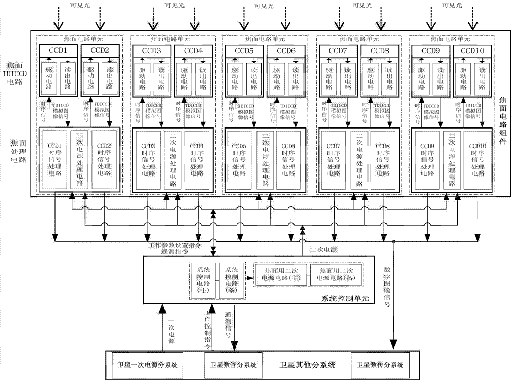
  • Circuit system of an optical remote sensor

Examples


Embodiment Construction

[0017] Optical remote sensors include four major systems: optics, mechanics, circuits, and heat. Among them, the mechanical system also becomes the focal plane structure of the optical remote sensor; the present invention is mainly designed for the circuit system, and adopts the circuit module integrated design method to minimize the number of single signal processors, and the direct electrical interface and interconnection cables of the single machine Corresponding reduction, power consumption, volume, and weight have been significantly optimized and improved to meet the lightweight design of high-resolution, large-width optical remote sensors.

[0018] Such as figure 1 As shown, the present invention includes a system control unit and a focal plane circuit assembly.

[0019] The system control unit is the control core of the entire optical remote sensor circuit system. Through communication with the satellite data management subsystem, the system control unit receives the w...


PUM


Abstract

A circuit system of an optical remote sensor relates to a space optical remote sensor. It includes system control unit and focal plane circuit components. The system control unit generates a working parameter setting instruction and sends it to the focal plane circuit assembly; the focal plane circuit assembly includes N parallel focal plane circuit units; each focal plane circuit unit includes a focal plane processing circuit and a focal plane TDICCD circuit, and the focal plane processing circuit Receive the working parameter setting instruction issued by the system control unit, and generate a timing signal to output to the focal plane TDICCD circuit; the focal plane TDICCD circuit generates a TDICCD analog image signal and sends it to the focal plane processing circuit; the focal plane processing circuit digitizes the TDICCD analog image signal After processing, it is sent to the external satellite data transmission subsystem. The invention has obvious improvements in volume, weight and power consumption, and can meet the design requirements of existing satellite loads for high-resolution and large-width optical remote sensors.

Description

technical field [0001] The invention relates to a space optical remote sensor, in particular to a circuit system of the optical remote sensor. Background technique [0002] In commercial and civil fields, optical remote sensing images have important application value in land, agriculture, urban planning, etc., and can be used for land and resources survey management, town planning, post-disaster assessment of natural disasters, and provide effective monitoring for post-disaster reconstruction, etc. and investigative tools. At present, it is difficult for domestic user units to purchase high-resolution and large-width optical remote sensing image data from abroad. In order to meet the growing demand for high-spatial and high-time-resolution remote sensing image data in my country's civilian fields, and to meet the needs of monitoring capabilities for specific targets and hotspot areas, the development of high-resolution and large-width optical remote sensor systems has becom...

Claims


Application Information

Patent Timeline
Patent Type & Authority Patents(China)
IPC IPC(8): H04N5/335H04N5/341H04N5/353
Inventor 张孝弘郑君张占东李浩洋丁晓燕李立金吕秋峰
Owner BEIJING RES INST OF SPATIAL MECHANICAL & ELECTRICAL TECH
Learn More