
Wheel bearing cap and wheel bearing

A technology of wheel bearing and wheel speed, applied in the field of wheel bearing, can solve the problems of firm connection, heavy weight, etc., and achieve the effect of reducing the tolerance chain

Inactive Publication Date: 2014-12-24
SCHAEFFLER TECH AG & CO KG
View PDF6 Cites 2 Cited by
  • Summary
  • Abstract
  • Description
  • Claims
  • Application Information

AI Technical Summary

Problems solved by technology

[0006] All in all, additional metal components such as plate rings and threaded inserts have to be firmly connected to the wheel bearing cap here in an expensive manner and also have a comparatively high weight.

Method used


Image

  • Wheel bearing cap and wheel bearing
  • Wheel bearing cap and wheel bearing
  • Wheel bearing cap and wheel bearing

Examples


Embodiment Construction

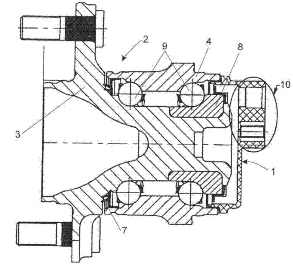
[0024] FIG. 1 shows a wheel bearing 2 of a vehicle, not shown, onto which a wheel bearing cap 1 is fitted. The wheel bearing cap 1 is constructed according to the prior art and is made of thermoplastic.

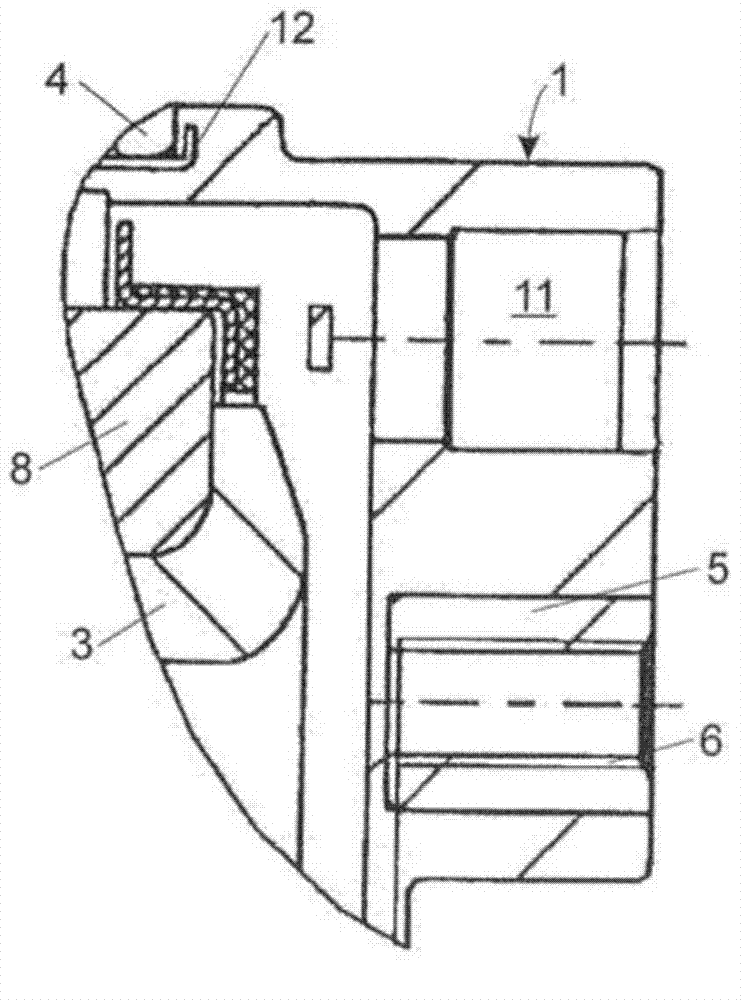
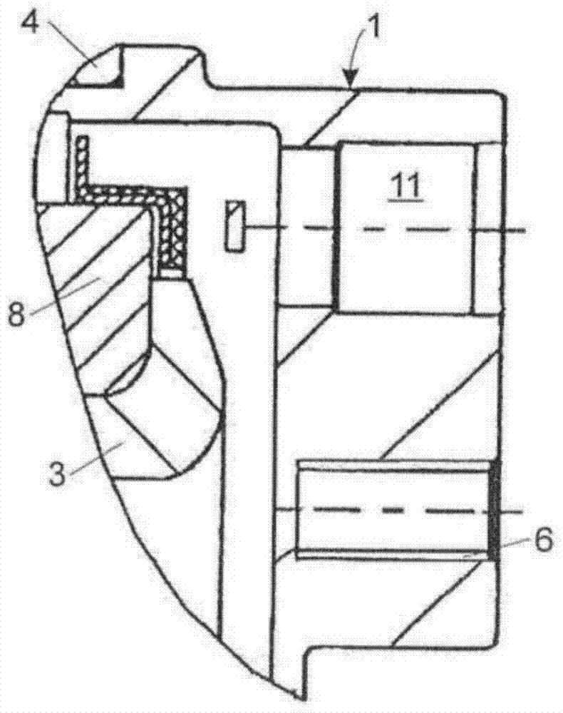
[0025] The wheel bearing 2 includes a flange inner ring 3 , which forms a slanted ball bearing 9 with a flange outer ring 4 arranged on a circumferential side and a bearing inner ring 8 . FIG. 2 shows a detail view of a section 10 of the wheel bearing cap 1 from FIG. 1 .

[0026] The inclined ball bearing 9 here comprises two rows of balls and a cage arranged between them. The bearing inner ring 8 is arranged on the circumference of the flange inner ring 3 and is surrounded by one of the two rows of balls.

[0027] Another row of balls surrounds the flange inner ring 3 and two rows of balls are surrounded by the flange outer ring 4 on the outside. A sealing element 7 is arranged in addition to the flange outer ring 4 and the flange inner ring 3 .

[0028] Holes for screws...


PUM


Abstract

The invention relates to a wheel bearing cap (1) for a vehicle, wherein a sensor unit can be inserted into the wheel bearing cap (1). The wheel bearing cap (1) is made of a plastic material, said plastic material being configured as a duroplast.

Description

technical field [0001] The invention relates to a wheel bearing cap for a vehicle having the features stated in the preamble of claim 1 and a wheel bearing having the features stated in the preamble of claim 8 . Background technique [0002] Wheel bearing caps for vehicles into which the sensor unit can be inserted are known from evident use experience. In this case, the wheel bearing cap is made of thermoplastic. [0003] In order for the bearing caps to remain securely mounted in their provided seats, these usually have a plate ring which is part of the bearing caps and which gives the bearing caps the necessary rigidity . [0004] For monitoring the rotational speed of a wheel it is known that the sensor unit can be arranged on the wheel bearing cap. In this case, the sensor unit is placed, for example, in a through-opening of the wheel bearing cap. [0005] In order to securely mount the sensor unit, a metal threaded insert can be provided in the wheel bearing cap, i...

Claims


Application Information

Patent Timeline
Patent Type & Authority Applications(China)
IPC IPC(8): B60B27/00
CPCB60B27/0068B60B27/0073B60B27/0084B60B2310/204B60B2360/30B60B2900/111B60B2900/115F16C19/186F16C33/723F16C41/007F16C2208/80F16C2326/02Y02T10/86
Inventor R·海斯A·凯泽F·艾歇尔曼W·瓦尔特A·黑普
Owner SCHAEFFLER TECH AG & CO KG
Learn More