Multi-port optical probe for photonic IC characterization and packaging

An end-face, cutting-edge technology, applied in the field of optical coupling, can solve problems such as difficult costs and achieve the effect of eliminating spacing mismatch

Pending Publication Date: 2021-07-23
SMART PHOTONICS HLDG BEVERAGE
View PDF6 Cites 0 Cited by
  • Summary
  • Abstract
  • Description
  • Claims
  • Application Information

AI Technical Summary

Problems solved by technology

This is difficult and costly, and fabricating fiber arrays is on the order of microns with precision, and achieving sub-micron precision requires careful selection of individual fibers

Method used


Image

  • Multi-port optical probe for photonic IC characterization and packaging
  • Multi-port optical probe for photonic IC characterization and packaging
  • Multi-port optical probe for photonic IC characterization and packaging

Examples


Embodiment Construction

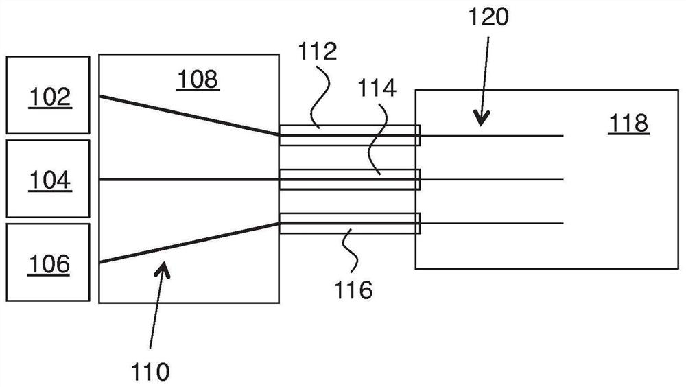
[0037] Figure 1A is a top view of an exemplary embodiment of the invention. In this example, number of optical fibers 102 , 104 , and 106 are optically coupled to photonic integrated circuit chip 118 via interposer unit 108 . Interposer unit 108 includes one or more flexible optical waveguide members, referred to herein as 112 , 114 and 116 . The flexible optical waveguide members each include an optical waveguide. These waveguides are shown here using thick black lines and are referred to as 110 . As shown, the flexible optical waveguide member is configured to be optically coupled between the on-chip optical waveguide 120 of the PIC chip 118 and the interposer unit 108 via the tip of the flexible optical waveguide member.

[0038] exist Figure 1A In the example of , the interposer unit provides the functionality to match the pitch of the array of optical fibers 102 , 104 , and 106 (ie, fiber-to-fiber spacing) to the pitch of the on-chip optical waveguide 120 . It is not...


PUM

PropertyMeasurementUnit
distanceaaaaaaaaaa

Abstract

Improved passive optical coupling to photonic integrated circuit (PIC) chips is provided. An interposer unit (108) having one or more flexible optical waveguide members (112, 114, 116) is employed. The flexible optical waveguide members are coupled to the PIC chip (118) via their tips. The PIC chip includes alignment features to facilitate lateral, vertical and longitudinal passive alignment of the flexible optical waveguide members to on-chip optical waveguides of the PIC.

Description

[0001] This application is a divisional application with the filing date of February 18, 2016, the application number of 201680011083.1, and the title of "Multiport Optical Probe for Photonic IC Characterization and Packaging". technical field [0002] The invention relates to optical coupling to photonic integrated circuit chips. Background technique [0003] Coupling optical fibers to photonic integrated circuit (PIC) chips is a difficult task, especially for multiple fiber connections at once. This is because the size of the optical field within the PIC waveguide is on the order of microns, which means that the fiber connections need to be positioned with sub-micron precision in three dimensions for optimal coupling. For the attachment of one or two fibers to a single PIC output / input waveguide there are standard methods which are extremely costly. However, there is no good, reliable and cheap solution for attaching multiple optical fibers to a single PIC chip. [0004]...

Claims


Application Information

Patent Timeline
Patent Type & Authority Applications(China)
IPC IPC(8): G02B6/42G02B6/14G02B6/26G02B6/30G02B6/36
CPCG02B6/30G02B6/368G02B6/305G02B6/4274G02B6/264G02B6/366G02B6/14
Inventor X·J·M·雷腾R·M·莱莫斯阿尔法雷斯多斯桑托斯
Owner SMART PHOTONICS HLDG BEVERAGE
Why Eureka
Try Eureka