Hybrid transmission

A technology of transmission and main transmission, applied in clutches, mechanical drive clutches, magnetic drive clutches, etc., can solve problems such as lack of comfort, and achieve the effect of saving structural space and effectively transmitting force

Inactive Publication Date: 2014-12-24
MAGNA POWERTRAIN AG & CO KG
View PDF7 Cites 12 Cited by
  • Summary
  • Abstract
  • Description
  • Claims
  • Application Information

AI Technical Summary

Problems solved by technology

Since shifting due to the transmission design is always associated with interruptions in traction, the following problem can arise in shifting transmissions of this type: In certain operating states, a lack of comfort can be felt due to the interruption of the drive torque due to the occurring vehicle vibrations.

Method used


Image

  • Hybrid transmission
  • Hybrid transmission
  • Hybrid transmission

Examples


Embodiment Construction

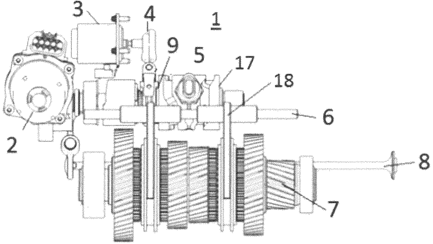
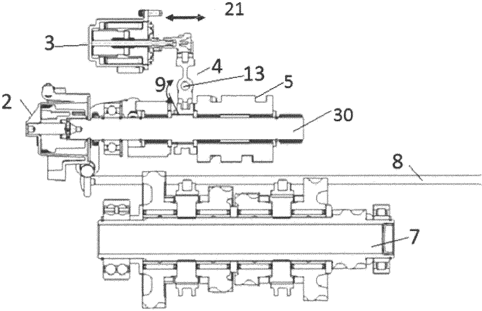
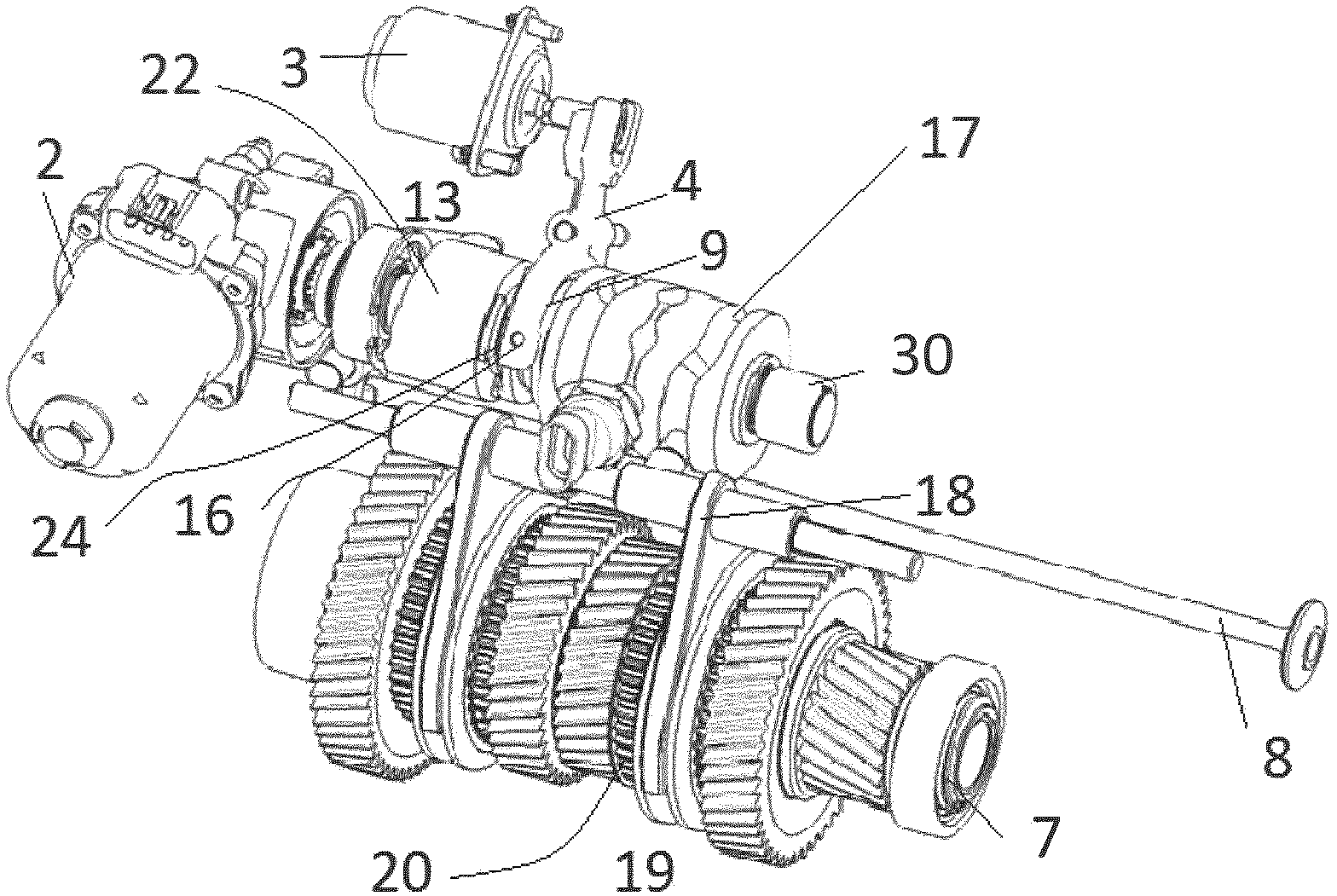
[0019] The figures show a hybrid transmission by way of example, important parts of the transmission, ie the transmission input shaft or layshaft, are not shown. In this type of transmission, the speed ratio is established by the gear pair and the torque is transmitted from the clutch to the transmission input shaft. The gears of each gear stage are installed on the transmission input shaft. The transmission output shaft or the transmission main shaft is arranged coaxially with the transmission input shaft. The gears of the two shaft pairs mesh with each other. Depending on the type of construction, the gears are either fixedly mounted on the shaft or freely rotatable but always axially fixed on the shaft. In order to create a force fit between the shaft and the freely rotating gear, said gear is fastened to the shaft by means of a jaw joint. The jaw engaging device is radially fixed and axially movable on a shaft supporting it. On the rim there is a tooth profile, the cou...


PUM


Abstract

The invention proposes a hybrid transmission having a main transmission shaft with gearwheels and having, arranged parallel thereto, a main shaft which has at least one shift drum, wherein the main shaft is driven by an actuator and has at least one shift slotted guide. The main shaft has an arrangement which can be activated both so as to connect the shift drum to a clutch and also so as to drive shift sleeves for at least one transmission stage.

Description

technical field [0001] A hybrid transmission is proposed which has a main transmission shaft with gearwheels and a parallel-arranged main shaft with at least one shift drum, wherein the main shaft is driven by an actuator and has at least one shift gate. The main shaft has devices that can be actuated for connecting the shift drum to the clutch and for actuating the shift sleeve for at least one gear stage. Background technique [0002] In most known automatic transmissions, the shifting and clutching functions are carried out individually via their own respective actuators. In many known shifting devices, the shifting and clutch actuation is carried out hydraulically. In order to realize the hydraulic shifting or clutch actuation, increased complexity arises, since a separate hydraulic actuator and possibly a pressure accumulator, lines, sensors and valves are required for each function. Increase the complexity of the system by using a hydraulic adjustment unit. [0003]...

Claims


Application Information

Patent Timeline
Patent Type & Authority Applications(China)
IPC IPC(8): F16H63/18
CPCF16D23/12F16D27/112F16D2023/141F16H61/32F16H63/18
Inventor 多米尼克·舍贝尔马库斯·比希勒丹尼尔·普里沃尔夫冈·施魏格尔
Owner MAGNA POWERTRAIN AG & CO KG
Why Eureka
Try Eureka