Non-contact sleeper identification method in moving state

An identification method and sleeper technology, applied in the field of rail transit, can solve the problems of missing data detection, slow sensing speed, and inability to realize sleeper identification, and achieve the effects of preventing sleeper misdetection and improving accuracy and precision.

Active Publication Date: 2019-03-26
四川铁拓科技有限公司
View PDF6 Cites 12 Cited by
  • Summary
  • Abstract
  • Description
  • Claims
  • Application Information

AI Technical Summary

Problems solved by technology

The proximity switch is a position switch that generates a switch pulse signal without direct contact with moving parts. It can sense the presence of metal. When the proximity switch is close to the metal, it will generate a switch signal. The system judges whether the position exists according to the switch signal. Sleeper, because the proximity switch can only detect metal, so this method can only realize the identification of the sleeper by detecting the existence of the spike, and the sleeper identification cannot be realized when the spike is lost, leaked or wrongly installed. In addition, due to the proximity switch The measuring range is short, the maximum is 4cm. Therefore, when installing, the distance between the proximity switch and the spike should be less than 4cm, while the distance between the base of the motion detection trolley and the spike exceeds 4cm. To detect the sleeper, the proximity switch must be extended. In this way, the proximity switch cannot be avoided from colliding with other objects, resulting in damage to the proximity switch or deviation of the installation position, thus making the proximity switch unable to work normally
Ultrasonic sensors use sound waves to detect sleepers. Ultrasonic waves can achieve long-distance measurement. Therefore, it is not necessary to install ultrasonic sensors outside the base of the motion inspection trolley during installation. However, ultrasonic waves have slow propagation speeds, small beam angles, and slow sensing speeds. Disadvantage, when the speed of the motion detection car is relatively fast, it is easy to cause missing data detection

Method used


Image

  • Non-contact sleeper identification method in moving state
  • Non-contact sleeper identification method in moving state
  • Non-contact sleeper identification method in moving state

Examples


Embodiment Construction

[0021] The present invention will be further described below in conjunction with the accompanying drawings and embodiments.

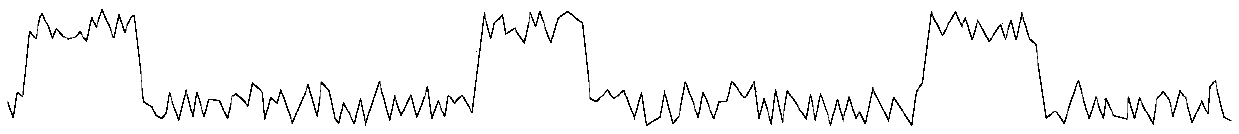
[0022] refer to figure 1 , a non-contact sleeper recognition method in a moving state of the present invention, comprising the steps of:

[0023] (1) Fix the laser sensor on the bottom surface of the main beam of the dynamic measuring trolley, the emitting surface of the laser sensor is coplanar with the bottom surface of the main beam of the trolley, and the laser aiming line is aligned with the rail platform or sleepers;

[0024] (2) The dynamic measuring trolley moves along the measuring line at a constant speed, and the laser sensor scans the sleeper and ballast bed below it, measures the distance between it and the sleeper and ballast bed, and records the collected raw data;

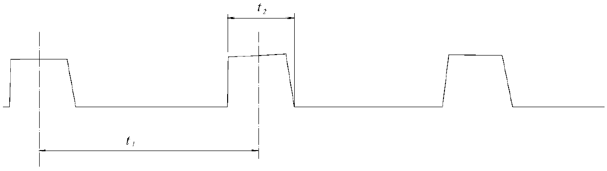
[0025] (3) Matching the laser sensor and the odometer to draw the original waveform diagram, the horizontal direction of the original waveform diagram is the mileage, and th...


PUM


Abstract

The invention discloses a non-contact sleeper identification method in a low-speed moving state, which can effectively improve the accuracy and precision of sleeper identification, rapidly detect thegeometrical state of the track, and prevent incorrect detection and missing detection of the sleeper. The non-contact sleeper identification method comprises the steps: fixedly arranging a laser sensor on the bottom surface of a main beam of a dynamic measuring trolley, wherein the emitting surface of the laser sensor is co-planar with the bottom surface of the main beam of the trolley, and the laser aiming line is aligned with a rail base or sleeper; pushing the dynamic measuring trolley according to a measuring path for enabling the laser sensor to scan the sleeper and a ballast bed below the laser sensor for measuring the distance between the laser sensor and the sleeper as well as the distance between the laser sensor and the ballast bed, and recording the acquired original data; matching the laser sensor with a speedometer to draw an original oscillograph, wherein the transverse direction of the original oscillograph stands for mileage, and the longitudinal direction of the original oscillograph stands for the distance between the laser sensor and the sleeper as well as the distance between the laser sensor and the ballast bed acquired by the laser sensor; performing data filtering on the original oscillograph for removing high-frequency signals to obtain a smooth oscillograph; measuring waveforms to obtain distance between adjacent wave crests t1 and wave crest width t2;and performing automatic identification on the sleeper by taking the distance between two adjacent wave crests t1 and the wave crest width t2 as constraint conditions.

Description

technical field [0001] The invention relates to rail transportation, in particular to a non-contact sleeper identification method in a low-speed moving state. Background technique [0002] The rapid detection technology of railway track geometric state is the development trend of railway track geometric state detection, and the dynamic track inspection trolley (abbreviated as dynamic inspection trolley) developed at home and abroad is the carrier of this technology. The motion inspection trolley integrates various sensors such as wireless communication, sleeper recognition, inertial navigation system, distance measurement, angle measurement, etc., and the sleeper recognizer is an important part of the motion inspection trolley. Its detection accuracy directly reflects the quality and quality of track detection. Accuracy, when a sleeper is missed or wrongly detected, it will directly affect the accuracy of all subsequent data detection and the detection quality of the entire ...

Claims


Application Information

Patent Timeline
Patent Type & Authority Applications(China)
IPC IPC(8): B61K9/02B61K9/08
CPCB61K9/02B61K9/08
Inventor 赵龙陈海军王国祥郑子天汤曦杨锋刘志鹏梅熙周世明
Owner 四川铁拓科技有限公司
Why Eureka
Try Eureka