Pipe double end chamfering machine

A double-head chamfering machine and pipe technology, which is applied to machine tool parts, metal processing machinery parts, clamping, etc., can solve the problems of labor hours and low efficiency, save time, improve processing efficiency, and reduce production costs and resource effects

Inactive Publication Date: 2014-12-31
天津市中马骏腾精密机械制造有限公司
View PDF0 Cites 13 Cited by
  • Summary
  • Abstract
  • Description
  • Claims
  • Application Information

AI Technical Summary

Problems solved by technology

When processing the inner and outer chamfers of the two ends of round pipe parts, the factory often uses a lathe to clamp and then pour two chamfers on one side, and turn the parts around and clamp and then process the two chamfers on the other side. This processing method is very traditional and efficient. Low, consumes too many man-hours

Method used


Image

  • Pipe double end chamfering machine
  • Pipe double end chamfering machine

Examples


Embodiment

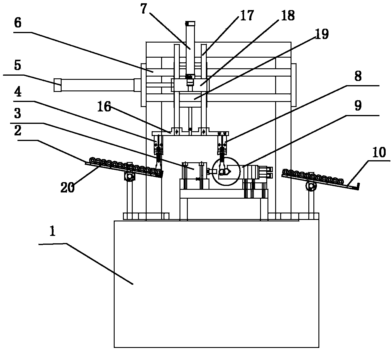
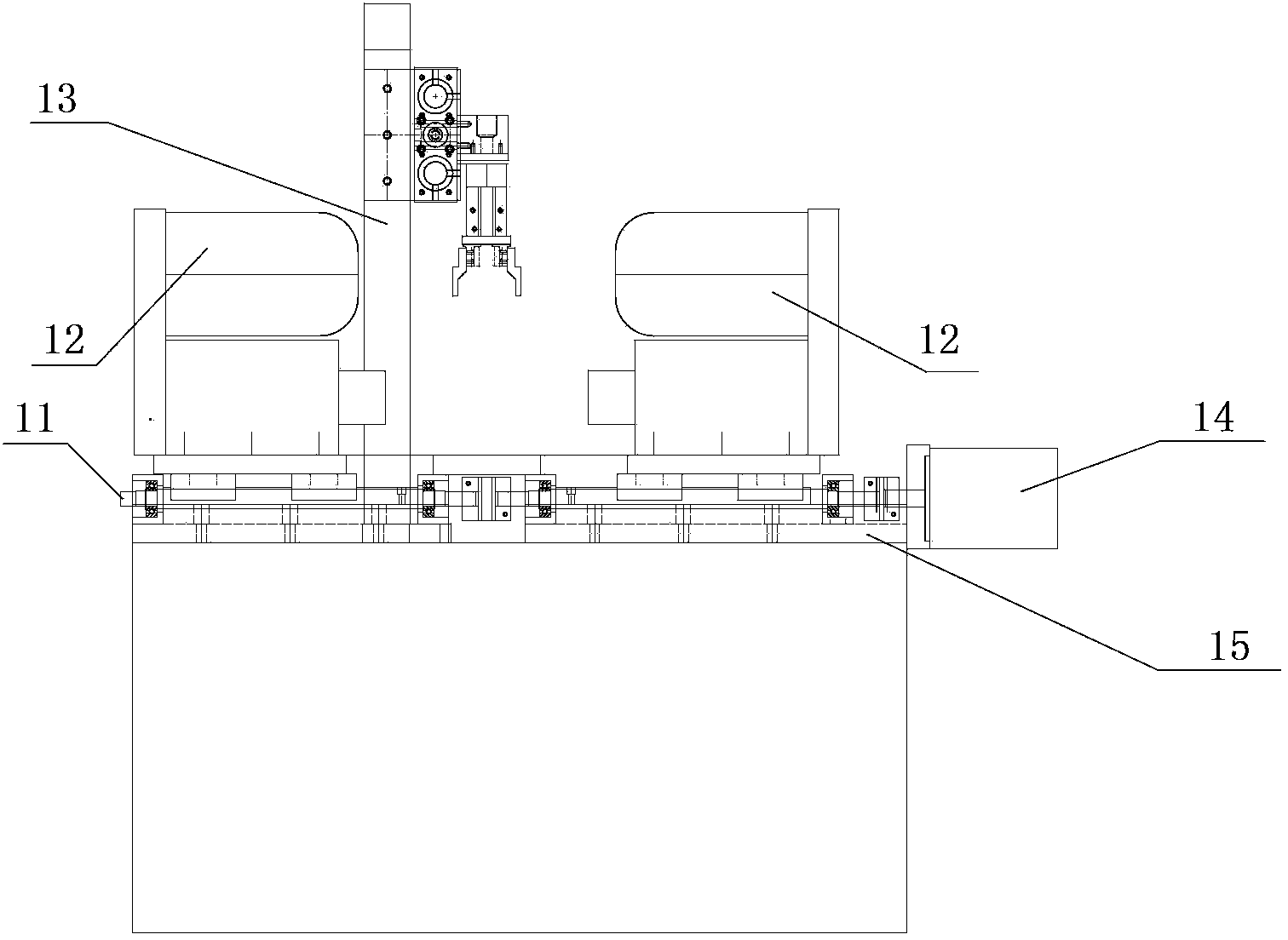
[0015] see attached figure 1 , 2 , the present invention provides a kind of pipe double-head chamfering machine, comprising a bed 1, a material loading and unloading mechanism, a chamfering processing mechanism, a clamping mechanism, an upper material bin 2, and an unloading material bin 10. The feeding mechanism, the chamfering processing mechanism and the clamping mechanism are fixed on the bed, the upper feeding bin is fixed on the left side of the bed, the lower feeding bin is fixed on the right side of the bed, and the feeding and unloading mechanism includes a vertical cylinder 7. Guide rail 6, horizontal cylinder 5, feeding pneumatic finger 4 and unloading pneumatic finger 8, the feeding pneumatic finger and unloading pneumatic finger are connected to the guide post 17 through the connecting bracket 16, and the guide post is connected to the vertical guide plate 18 is slidingly connected, the connecting bracket is connected with the vertical cylinder 7, the horizontal ...


PUM


Abstract

The invention relates to a pipe double end chamfering machine which comprises a lathe body, a charging and discharging mechanism, a chamfering mechanism, a clamping mechanism, a charging bin and a discharging bin, wherein the charging and discharging mechanism, the chamfering mechanism and the clamping mechanism are fixedly arranged on the lathe body; the charging and discharging mechanism comprises a vertical cylinder, a guide rail, a horizontal cylinder and a charging and discharging pneumatic finger; the charging and discharging pneumatic finger is connected with a guide post by virtue of a connecting bracket; the guide post is slidably connected with a vertical guide plate; the connecting bracket is connected with the vertical cylinder; the horizontal cylinder is connected with a horizontal guide plate; the horizontal guide plate is slidably connected with the guide rail; the horizontal guide plate is fixedly connected with the vertical guide plate; The clamping mechanism is arranged on the lathe body between the charging bin and the discharging bin. The pipe double end chamfering machine has the beneficial effects of realizing full-automatic operations such as charging, chucking, processing and discharging, processing four chamfer angles inside and outside two end surfaces by virtue of once chucking, conveniently regulating the processing frequency and the tool feeding depth by virtue of PLC (Programmable Logical Controller) control over equipment and realizing full-automatic production.

Description

technical field [0001] The invention belongs to a special machining machine tool, in particular to a double-head chamfering machine for pipes. Background technique [0002] Round pipe parts are machined with internal and external chamfering at both ends, which is widely used in double-end chamfering processing of round pipe parts in various industries. When processing the inner and outer chamfers of the two ends of round pipe parts, the factory often uses a lathe to clamp and then pour two chamfers on one side, and turn the parts around and clamp and then process the two chamfers on the other side. This processing method is very traditional and efficient. Low, consumes too many man-hours. In order to improve the processing efficiency of internal and external chamfering of both ends of pipe parts. Contents of the invention [0003] The present invention aims to overcome the deficiencies in the prior art, and provides a pipe type double-head chamfering machine, which can r...

Claims


Application Information

Patent Timeline
Patent Type & Authority Applications(China)
IPC IPC(8): B23Q7/04B23Q3/08B23Q5/40
CPCB23Q7/04B23Q3/082B23Q5/402B23Q2240/007
Inventor 杜辰张钧王文春王同义闫琳
Owner 天津市中马骏腾精密机械制造有限公司
Why Eureka
Try Eureka