Coating machine feeding system

A technology of feeding system and coating machine, which is applied in the direction of coating and liquid coating device on the surface, etc., which can solve the problems of high labor intensity, low feeding efficiency, difficult mass processing of coating machines, etc.

Active Publication Date: 2014-04-30
NINGBO CRRC NEW ENERGY TECH CO LTD
View PDF6 Cites 3 Cited by
  • Summary
  • Abstract
  • Description
  • Claims
  • Application Information

AI Technical Summary

Problems solved by technology

[0002] When producing electrodes, it is necessary to coat the electrode material on the substrate, and the coating of the electrode material on the substrate needs to be realized by a coating machine. The coating machine includes a slurry tank, a coating roller, a doctor roller and an oven. After the material is added to the slurry tank, the coating roller and the scraper roller work, the substrate is driven by the coating roller and coated with the slurry by the scraper roller, and then the substrate coated with the slurry is dried in an oven to obtain a finished product Electrodes. At present, manual or semi-automatic methods are generally used to add slurry to the slurry tank of the coating machine. These methods have low feeding efficiency, high labor intensity, and high requirements for the operator's operation level, making the coating machine Difficult to achieve mass processing

Method used


Image

  • Coating machine feeding system
  • Coating machine feeding system
  • Coating machine feeding system

Examples


Embodiment Construction

[0014] The present invention will be described in further detail below in conjunction with the accompanying drawings and specific embodiments.

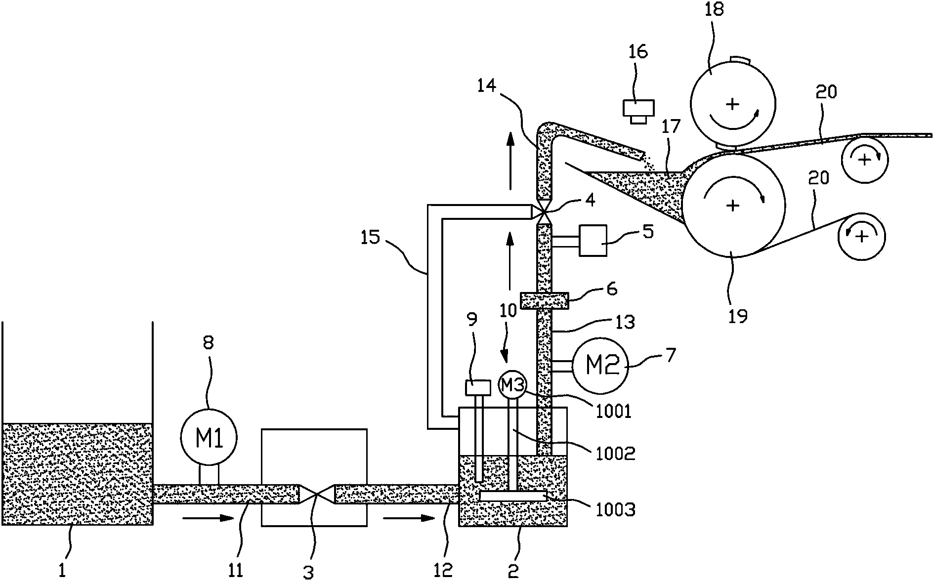
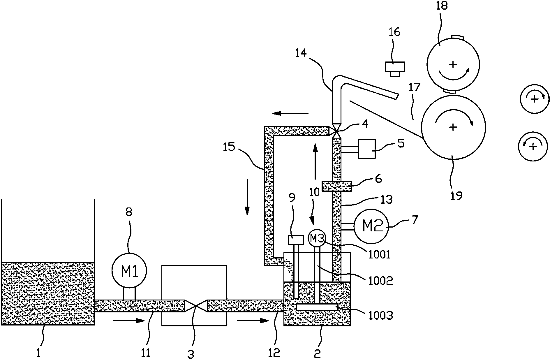
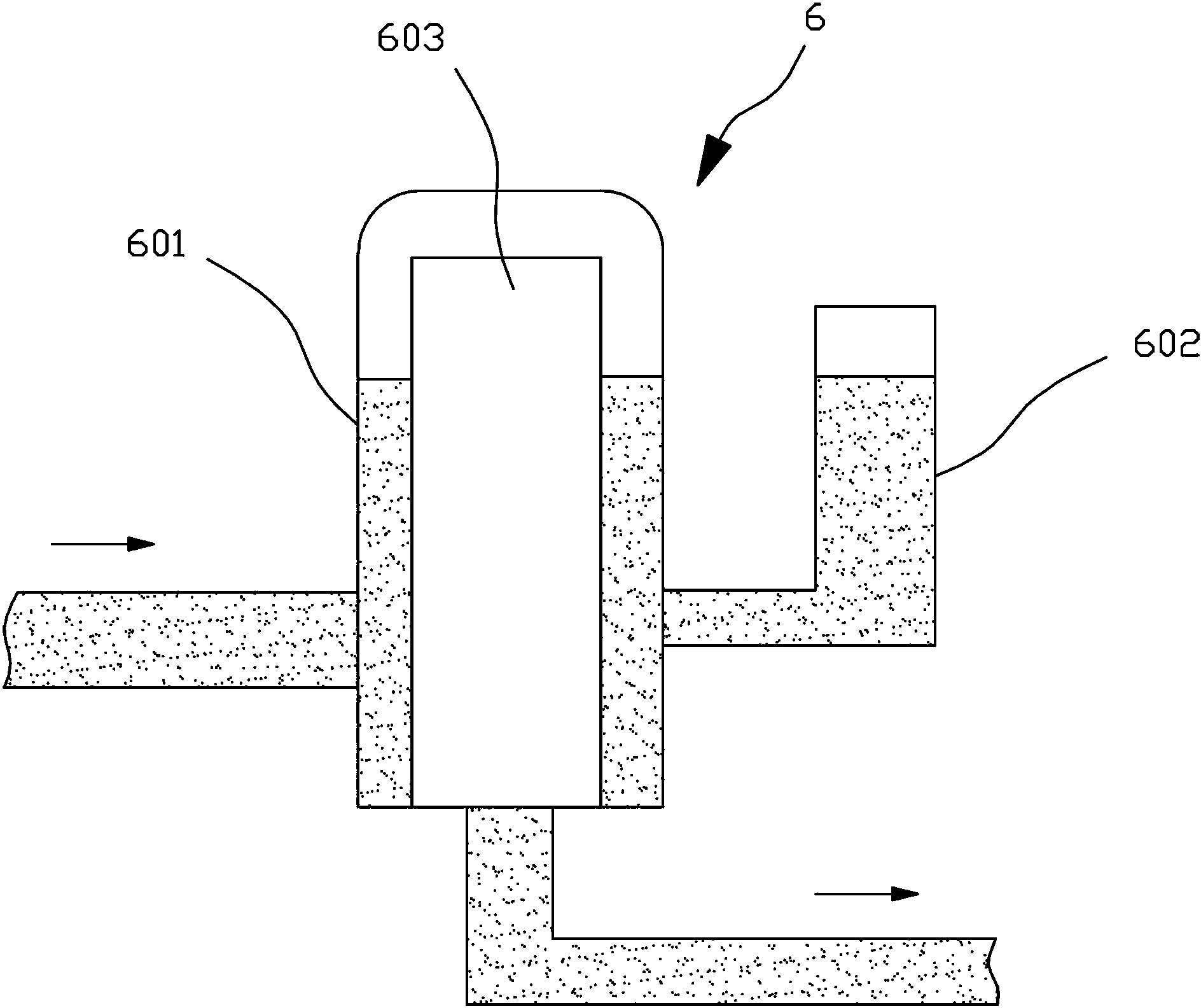
[0015] Depend on figure 1 , figure 2 , image 3 with Figure 4 As shown, the feeding system of the coating machine of the present invention includes a slurry tank 1 for holding the slurry used for coating, a material loading tank 2, a valve 3 with an inlet and an outlet, and three valves with an inlet and two outlets. Directional valve 4, the first liquid level sensor 9 used to detect the liquid level of the upper material tank 2 and the second liquid level sensor 16 used to detect the liquid level of the slurry tank 17, the valve 3 is a two-way valve, and the slurry The inlet of the material barrel 1 and the valve 3 is connected through the first pipeline 11, the outlet of the valve 3 is connected with the upper material barrel 2 through the second pipeline 12, and the inlet of the upper material barrel 2 and the three-way valve ...


PUM


Abstract

The invention discloses a coating machine feeding system. The coating machine feeding system comprises a slurry barrel used for containing slurry for coating, a feeding bucket, a valve with an inlet and an outlet, a three-way valve with an inlet and two outlets, a first liquid level sensor used for detecting the liquid level of the feeding bucket, and a second liquid level sensor used for detecting the liquid level of a slurry tank, wherein the slurry barrel is connected with the inlet of the valve through a first pipeline; the outlet of the valve is connected with the feeding bucket through a second pipeline; the feeding bucket is connected with the inlet of the three-way valve a third pipeline; one outlet of the three-way valve extends to the slurry tank or the upper part of the slurry tank through a fourth pipeline; the other outlet of the three-way valve is connected with the feeding bucket through a fifth pipeline; a first motor is arranged on the first pipeline or the second pipeline; a second motor and a pressure sensor are arranged on the third pipeline. According to the system, the full-automatic feeding can be realized, so that the feeding efficiency is high, and coating machines can be processed in batch.

Description

technical field [0001] The invention relates to a coating machine feeding system. Background technique [0002] When producing electrodes, it is necessary to coat the electrode material on the substrate, and the coating of the electrode material on the substrate needs to be realized by a coating machine. The coating machine includes a slurry tank, a coating roller, a doctor roller and an oven. After the material is added to the slurry tank, the coating roller and the scraper roller work, the substrate is driven by the coating roller and coated with the slurry by the scraper roller, and then the substrate coated with the slurry is dried in an oven to obtain a finished product Electrodes. At present, manual or semi-automatic methods are generally used to add slurry to the slurry tank of the coating machine. These methods have low feeding efficiency, high labor intensity, and high requirements for the operator's operation level, making the coating machine It is difficult to re...

Claims


Application Information

Patent Timeline
Patent Type & Authority Applications(China)
IPC IPC(8): B05C11/10
Inventor 张凯傅冠生阮殿波张洪权陈照平吴震寰
Owner NINGBO CRRC NEW ENERGY TECH CO LTD
Why Eureka
Try Eureka