Suspension Arms for Motor Vehicles

A technology for motor vehicles and suspension arms, which is applied in the field of suspension arms for motor vehicles, and can solve the problems of rigidity (insufficient strength, etc.)

Active Publication Date: 2016-09-28
KOBE STEEL LTD
View PDF8 Cites 0 Cited by
  • Summary
  • Abstract
  • Description
  • Claims
  • Application Information

AI Technical Summary

Problems solved by technology

[0011] However, the suspension arm for a vehicle using the L-shaped arm portion having the above-mentioned H-shaped cross-sectional structure has the following problem. Mode design (i.e., with sufficient in-plane bending stiffness), but design of vibrational modes based on out-of-plane moments predominantly generated at low-order (e.g., primary and secondary) natural frequencies is not sufficiently considered
That is, there is a problem of insufficient out-of-plane bending rigidity (strength)
[0012] In addition, since the suspension arm for a vehicle using the L-shaped arm portion having the U-shaped cross-sectional structure disclosed in the above-mentioned Patent Document 4 adopts a cross-sectional structure that cannot be manufactured by cheap forging, it is necessary to Issues such as manufacturing by casting

Method used


Image

  • Suspension Arms for Motor Vehicles
  • Suspension Arms for Motor Vehicles
  • Suspension Arms for Motor Vehicles

Examples


Embodiment approach 1

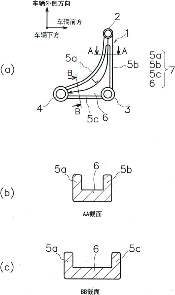
[0056] figure 1 (a) is a top view, (b) is an AA cross-sectional view of the arm, and (c) is a BB cross-sectional view of the arm. exist figure 1 In the coordinate system shown in (a), the "vehicle outer direction" facing upward in the paper refers to, for example, the axle side, and the "vehicle front" facing right in the paper refers to the direction in which the vehicle travels forward as described in the text. , "under the vehicle" in a direction perpendicular to the paper surface refers to a direction in which the vehicle side is viewed from the road surface side under the vehicle. Figure 2 to Figure 8 This definition also applies generically.

[0057] figure 1In (a), 1 is a suspension arm for a vehicle having an L-shaped arm portion 7 in a plan view, 2 is a ball joint support portion attached to the axle side of the vehicle, and 3 is a vehicle body mounted on the side of the vehicle body. The bush support part A of the side engagement part, 4 is the bush support part...

Embodiment approach 2

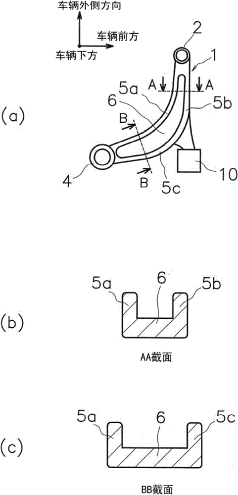
[0068] image 3 A suspension arm for a vehicle according to Embodiment 2 of the present invention (invention example 2 in Table 1 above) having the same U-shaped cross-sectional shape as Embodiment 1 is shown, (a) is a plan view, and (b) is an arm portion AA cross-sectional view, (c) is a BB cross-sectional view of the arm. In the present embodiment, parts based on basically the same technical idea as those in Embodiment 1 are given the same reference numerals and detailed descriptions thereof are omitted, and different parts are described in detail.

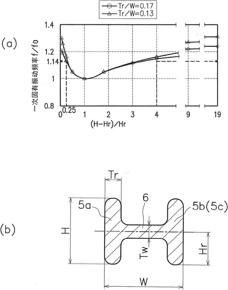
[0069] image 3 In (a), 10 is an in-plane bushing support portion C that is attached to the vehicle body side and is coupled to the middle of the arm portion 7 as a vehicle body side engagement portion. Furthermore, in this embodiment, the width of the web 6 in the vicinity of the middle of the arm portion 7 is smaller than in the first embodiment. In this case, even if Tr / W is fixed as in Embodiment 1 and the ratio of (H-Hr)...

Embodiment approach 3

[0071] Figure 4 A suspension arm for a vehicle according to Embodiment 3 of the present invention (invention example 3 in the above-mentioned Table 1) having a U-shaped cross-sectional shape similar to Embodiments 1 and 2 is shown, (a) is a plan view, and (b) is an arm AA sectional view of the part, (c) is a BB sectional view of the arm. In the present embodiment, parts based on basically the same technical idea as those in Embodiment 1 are given the same reference numerals and detailed descriptions thereof are omitted, and different parts are described in detail.

[0072] Figure 4 In (a), 20, 21, 22, 23, 24 are respectively arranged in the above-mentioned figure 1 Shown are holes in the web 6 for lightweighting of the suspension arm for a motor vehicle. In this case, Tr / W was fixed as in Invention Example 1, and the ratio of (H-Hr) / Hr was 19, and a result close to Invention Example 1 was obtained. That is, if 4≦(H-Hr) / Hr≦19 shown in the above formula (2) is satisfied, a...


PUM


Abstract

An L-shape vehicular suspension arm includes a unitary body forged from an aluminum alloy. The unitary body includes a web and ribs. The web is substantially planar, and the ribs extend from surfaces of the web at peripheral edges of the web. In cross-section, at least one part of the unitary body has a U-shape, an H-shape, or an inverted U-shape, such that dimensions of the unitary body satisfy expression (1) or (2): 0.05≦̸(H−Hr) / Hr≦̸0.25  (1) 4≦̸(H−Hr) / Hr≦̸19  (2) where H is a total height of the unitary body, and Hr is a height from a center of the web to a lowermost point of the unitary body.

Description

technical field [0001] The present invention relates to a suspension arm for a motor vehicle produced by forging. Background technique [0002] Conventionally, it is known that an automotive suspension arm having an L-shaped arm portion in a plan view is used in strut suspensions and double wishbone suspensions (motor vehicle running parts), which have the functions of improving ride comfort, The advantages of driving stability and being able to reduce the unsprung load (refer to Patent Documents 1 to 3). [0003] It is known that the automotive suspension arm having the above-mentioned L-shaped arm part mainly receives input from the front-rear direction of the motor vehicle (hereinafter, also referred to as "vehicle"). In order to reduce the moment (that is, the moment acting in the plane perpendicular to the vertical direction of the vehicle), it is necessary to adopt an H-shaped cross-sectional structure that can increase the in-plane bending rigidity. [0004] In addi...

Claims


Application Information

Patent Timeline
Patent Type & Authority Patents(China)
IPC IPC(8): B60G7/00
CPCB60G7/001B60G2206/122B60G2206/13B60G2206/16B60G2206/81022C22F1/04
Inventor 细井宽哲
Owner KOBE STEEL LTD
Why Eureka
Try Eureka