
Multipurpose ship berthing device

A multi-purpose, ship-based technology, applied in ship cleaning devices, ship hulls, ship construction, etc., can solve problems such as large impact force of tires, frictional collision between ship hull and wharf, water pollution, etc., to increase friction coefficient, improve safety, The effect of reducing the impact force

Inactive Publication Date: 2014-12-31
CHANGSHA UNIVERSITY OF SCIENCE AND TECHNOLOGY
View PDF6 Cites 19 Cited by
  • Summary
  • Abstract
  • Description
  • Claims
  • Application Information

AI Technical Summary

Problems solved by technology

But there are many defects in utilizing waste tires as the anti-collision decompression device: 1, when the ship is docked, because the ships are still in motion, and the waste tires are fixed, only when the ships are close to the shore, the waste tires just play a role. Protective effect, the ship has a great impact on the tires, and there will be greater friction between the waste tires and the ship, which will still cause damage to the ship's surface; The effect is limited, especially under the action of strong transverse wind, when the ship docks too fast, the existing fixed protection device often cannot effectively protect the hull and the pile platform in front; Into the water causing water pollution
The above-mentioned berthing method has the following disadvantages: 1. It requires multiple people to operate at the same time, which is time-consuming and labor-intensive, and there is a certain risk; 2. The position of the ship's berthing is not very accurate, and friction and collision between the hull and the dock often occur

Method used


Image

  • Multipurpose ship berthing device
  • Multipurpose ship berthing device
  • Multipurpose ship berthing device

Examples


Embodiment Construction

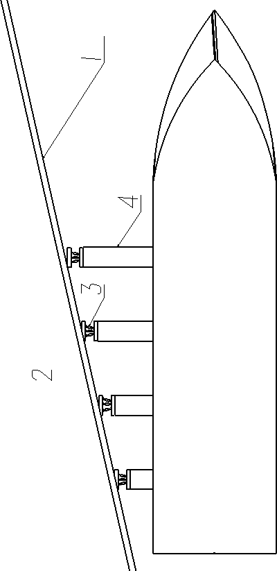
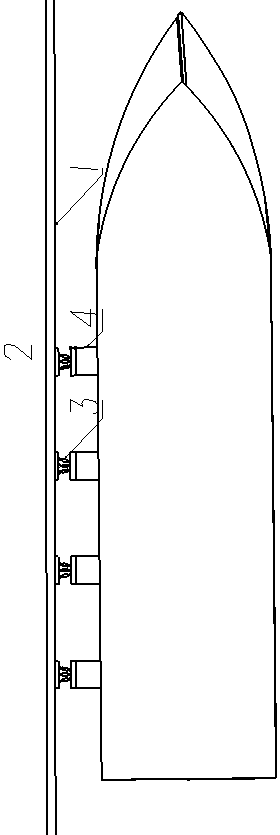
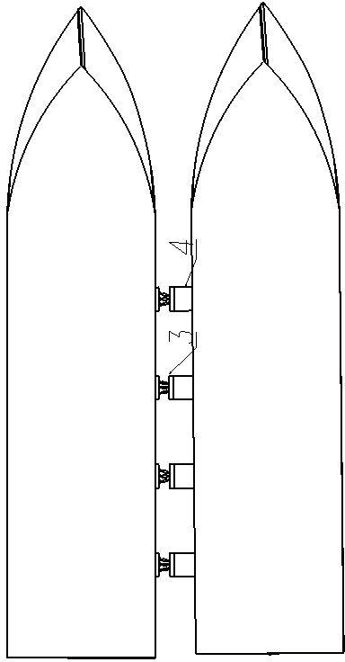
[0021] See figure 1 , which is a schematic diagram of a berthing dock for a multi-purpose ship berthing device according to the present invention, including a hull, a primary decompression device and a secondary decompression slow pulling device 3, and the primary decompression device includes one or A plurality of double-acting single-piston oil cylinders, and a control room is installed in the hull. The piston rod 4 of each double-acting single-piston oil cylinder can extend out of the hull and be adsorbed on the outer steel plate (or magnetic adsorption device) 1 of the wharf 2. The outer end of the piston rod 4 is fixed with an electromagnet 5, and the expansion and contraction of the piston rod 4 in each double-acting single-piston oil cylinder and whether the electromagnet 5 is energized are controlled by the hydraulic system.

[0022] The laser displacement sensor is installed on the secondary decompression and slow pulling device 3, and the distance and speed signals o...


PUM


Abstract

The invention discloses a multipurpose ship berthing device. The multipurpose ship berthing device is characterized in that the multipurpose ship berthing device comprises one or more double-acting single-piston oil cylinders arranged in a ship; an electromagnet is fixed at the outer end of each piston rod; a hydraulic system controls extension of the piston rods in the double-acting single-piston oil cylinders and controls power-on / power-off of the electromagnets. Secondary depression slow pulling devices are mounted at the front ends of the piston rods respectively. When a large ship is docked, each piston rod extends outwards under the action of the oil cylinders, and the ship gradually approaches the shore side of a wharf; the electromagnets are powered on to generate powerful magnetic force, the front ends of the electromagnets are enabled to be tightly adhered to the shore side of the wharf, and the ship is slowly docked toward the wharf under the action of the multiple piston rods to finally approach the wharf smoothly, so that the impact force of the ship to the wharf during docking is greatly reduced, and the safety of the wharf is guaranteed. The device is applicable to mutual berthing among offshore ships, and effective transverse safety mooring between two ships is realized.

Description

technical field [0001] The invention relates to the field of ship equipment, in particular to a multi-purpose ship berthing device technology. Background technique [0002] At present, in order to alleviate the contradiction between the insufficient handling capacity of the wharf design and the increasing production demand, it is often necessary to strengthen the structural transformation of the old wharf and improve the adaptability of the old wharf to new ship types; in addition, many port projects are currently under construction. , the impact force generated by the ship berthing, the mooring force generated by the offshore wind after the ship berthed, and the ship squeeze force generated by the onshore wind are three common dock dynamic loads. This lateral force has a particularly significant impact on high-piled wharves and deep-water open wharfs, and must be considered in wharf structural design and safe operation. [0003] In order to prevent the ship from collidin...

Claims


Application Information

Patent Timeline
Patent Type & Authority Applications(China)
IPC IPC(8): B63B59/00
Inventor 蒋昌波段自豪陈杰肖政李玉墩赵静管喆
Owner CHANGSHA UNIVERSITY OF SCIENCE AND TECHNOLOGY
Learn More