Speed-adjustable self-cleaning conveyor

A self-cleaning, conveyor technology, applied in the direction of conveyors, conveyor objects, cleaning devices, etc., can solve the problems of easy wear, damage, and poor scraping effect of scrapers, so as to avoid damage, reduce production costs, and reduce parts Effect

Inactive Publication Date: 2014-12-31
HUZHOU QIANJIN BAOYUN MACHINERY CASTING
View PDF0 Cites 8 Cited by
  • Summary
  • Abstract
  • Description
  • Claims
  • Application Information

AI Technical Summary

Problems solved by technology

The main structure of the cleaning device is an alloy scraper. The alloy scraper is fixed on the steel pipe through the cleaning support plate. One end of the scraper is vertically attached to the tape surface. The tape runs horizontally, and the resistance of the scraper to the adherend is horizontal. In this way, when the scraper scrapes off the adhesion, the adhesion will usually accumulate horizontally on the tape surface, and the cleaning effect is not ideal, especially when it encounters hard objects, it is easy to cause damage to the scraper or the tape; the belt machine conveys materials The speed of the cleaning device affects the effect of scraping off the adherents. If the conveying speed is too high, the scraper will be more likely to wear. The speed of conveying materials is fixed, and it is impossible to choose the conveying speed suitable for scraping off the adherents

Method used


Image

  • Speed-adjustable self-cleaning conveyor
  • Speed-adjustable self-cleaning conveyor
  • Speed-adjustable self-cleaning conveyor

Examples


Embodiment 1

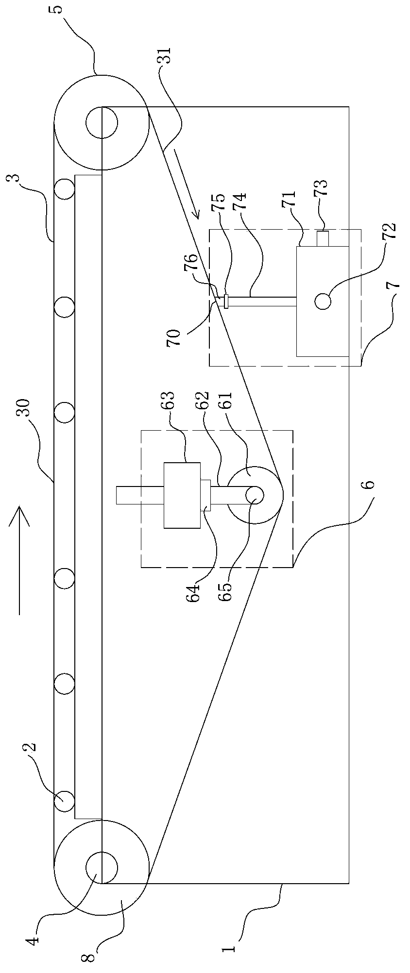
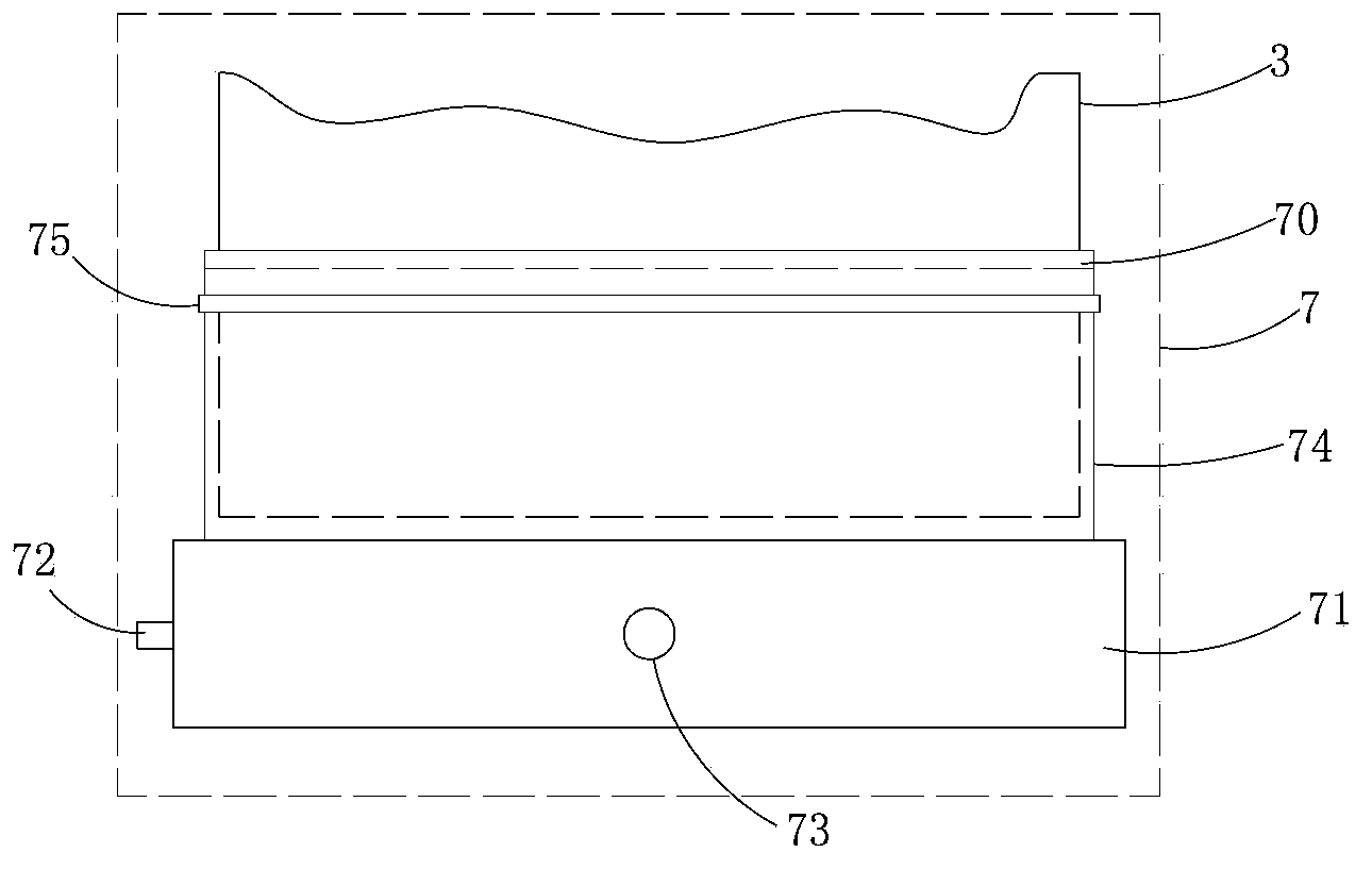
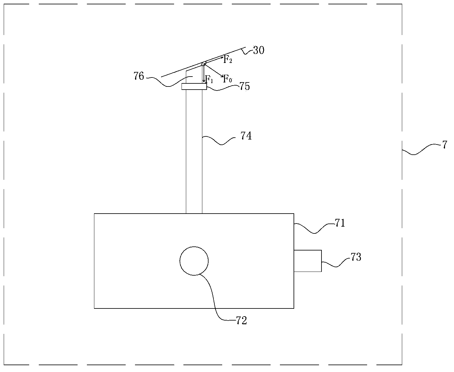
[0030] Example 1. A speed-adjustable self-cleaning conveyor constructed as Figure 1-3 As shown, it includes a frame 1, and the frame 1 is provided with a driving device 4, a driving roller 8, a reversing roller 5, an idler group 2, a conveyor belt 3, and also includes an adjusting device 6 and a cleaner 7, and the adjusting device 6 is set Under the frame 1, the conveying tape 3 is supported downwards to make it triangular. The conveying tape 3 includes an upper part 30 positioned on the top surface of the frame 1 for conveying materials and a lower part 31 positioned below the frame 1. The adjusting device 6 Adjust the tension of conveying tape 3 by moving up and down; Cleaner 7 is arranged below the lower part 31 of conveying tape and near the conveyor discharge port, and sweeper 7 has a bottom surface parallel with the lower part 31 of conveying tape The cleaning surface 70 is connected to the drive device 4 with the frequency converter 9 .

[0031] like figure 1 As sho...


PUM


Abstract

The invention discloses a speed-adjustable self-cleaning conveyor. The speed-adjustable self-cleaning conveyor comprises a rack, an adjusting device and a sweeper, wherein the rack is provided with a driving device, a transmission drum, a turnabout drum, a supporting roller group and a conveying rubber belt; the adjusting device is arranged under the rack and is used for downwards supporting the conveying rubber belt and enabling the conveying rubber belt to be in a triangular shape, the conveying rubber belt comprises an upper part which is positioned on the top surface of the rack and is used for conveying materials and a lower part which is positioned under the rack, and the adjusting device is used for adjusting the tensioning degree of the conveying rubber belt through the up-and-down moving of the adjusting device; the sweeper is arranged under the lower part of the conveying rubber belt and is close to a material outlet of the conveyor, and the sweeper is provided with a sweeping surface which is parallel to the bottom surface of the lower part of the conveying rubber belt; the driving device is connected with a frequency converter. According to the speed-adjustable self-cleaning conveyor disclosed by the invention, the adjusting device in the technical scheme is used for adjusting the tensioning degree of the conveying rubber belt and is also used for enabling the conveying rubber belt and the horizontal surface to be in an included angle, thus objects adhered to the conveying rubber belt can be well scraped by the sweeper, double functions can be obtained, the components of the whole conveyor are reduced, and the production cost is reduced.

Description

technical field [0001] The invention relates to the technical field of transportation machinery, in particular to a speed-adjustable self-cleaning conveyor. Background technique [0002] The belt conveyor is an efficient continuous transportation equipment, which is mostly used to transport bulk materials. It is very important to clean the loading surface of the belt to avoid the loss of materials and the pollution caused. [0003] When the tape machine is working, after the material conveyed by the tape machine is unloaded by the head roller, a small part will often adhere to the tape working surface. This will affect the working efficiency of the entire tape machine, and will cause environmental pollution and reduce the service life of the product. [0004] Most of the current belt conveyors have been equipped with cleaning devices to clean the materials adhered to the tape bearing surface, so as to prevent the adhesives on the tape from polluting the environment and caus...

Claims


Application Information

Patent Timeline
Patent Type & Authority Applications(China)
IPC IPC(8): B65G23/44B65G45/12B65G23/24
Inventor 沈文宝
Owner HUZHOU QIANJIN BAOYUN MACHINERY CASTING
Why Eureka
Try Eureka