Preparation method of sensing ring capable of reducing optic fiber gyroscope temperature drift

A technology of temperature drift and fiber optic gyroscope, applied in gyroscope/steering sensing equipment, Sagnac effect gyroscope, measuring device, etc., can solve the problems of optical performance damage, ring performance degradation, zero drift, etc., to achieve Effects of reducing temperature drift, improving temperature performance, and suppressing phase error

Active Publication Date: 2014-12-31
BEIJING AUTOMATION CONTROL EQUIP INST
View PDF4 Cites 22 Cited by
  • Summary
  • Abstract
  • Description
  • Claims
  • Application Information

AI Technical Summary

Problems solved by technology

According to different mechanical strength, thermal parameters and weight requirements, the skeleton can usually be made of aluminum alloy or titanium alloy material, but these materials have a certain thermal expansion coefficient, which cannot be perfectly matched with the optical fiber and curing glue, and because the optical fiber is under a certain tension If it is wound on the surface of the skeleton, if it is subjected to the thermal expansion stress of the skeleton, the tension value of the fiber will increase and the

Method used


Image

  • Preparation method of sensing ring capable of reducing optic fiber gyroscope temperature drift
  • Preparation method of sensing ring capable of reducing optic fiber gyroscope temperature drift
  • Preparation method of sensing ring capable of reducing optic fiber gyroscope temperature drift

Examples


Embodiment 1

[0030] step 1

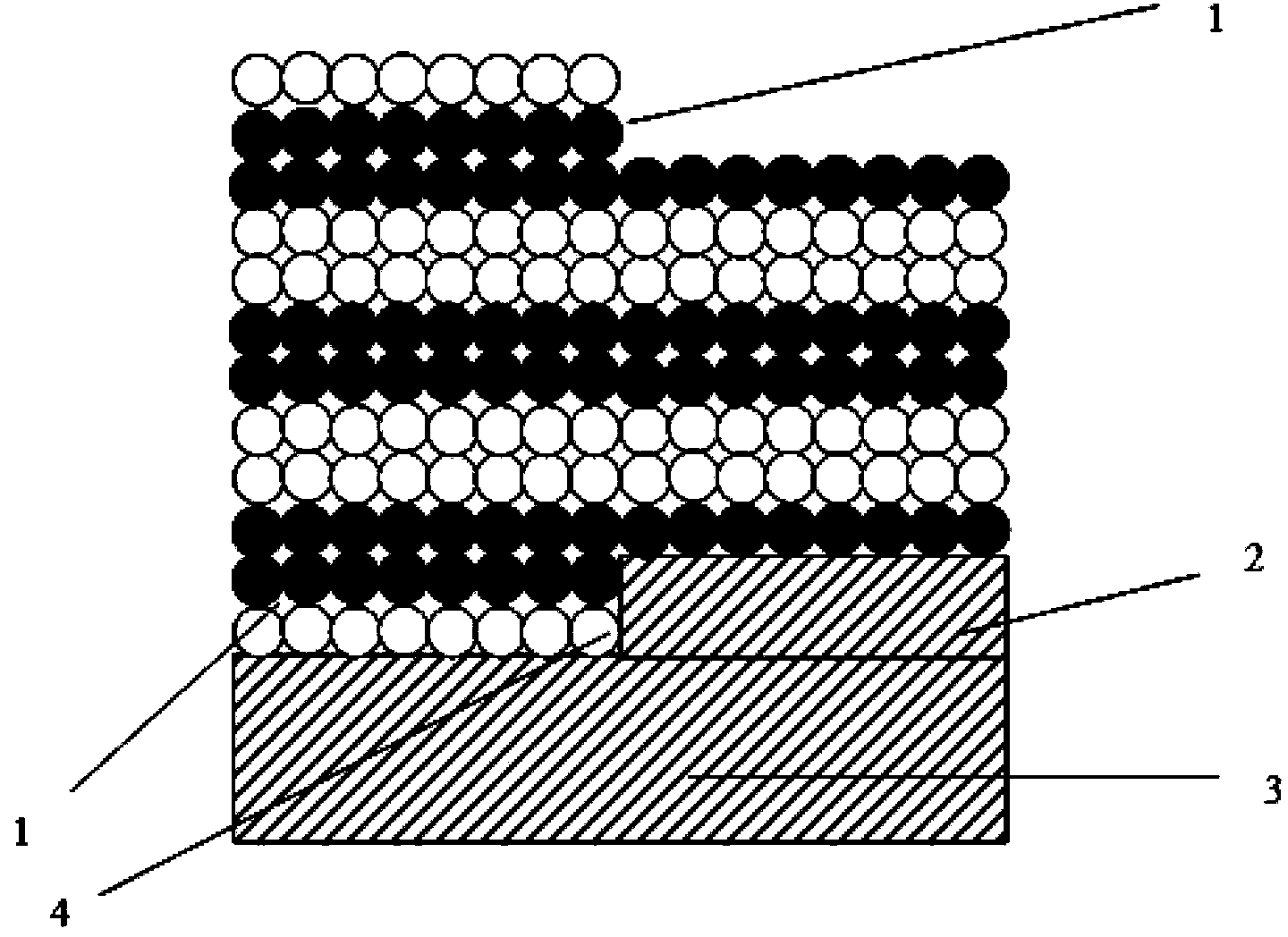
[0031] Install the winding tooling on the two-layer stepped ring skeleton, and wind the polarization-maintaining optical fiber according to the quadrupole symmetrical winding method:

[0032] Take a moderately long polarization-maintaining optical fiber and wind it from the midpoint of the entire optical fiber. The winding starting point 4 is located at figure 1 The boundary between the two steps of the ring frame shown; the optical fiber on the side of the midpoint rotates clockwise to the left edge of the ring frame until it reaches the leftmost edge of the lower first step, completing the second step in the first step One layer of optical fiber winding; the optical fiber on the other side of the midpoint rotates counterclockwise to the left of the ring frame until it reaches the leftmost edge of the first step, completing the winding of the second layer of optical fiber in the first step, and then the other Continue to wind counterclockwise to the right unt...

Embodiment 2

[0037] step 1

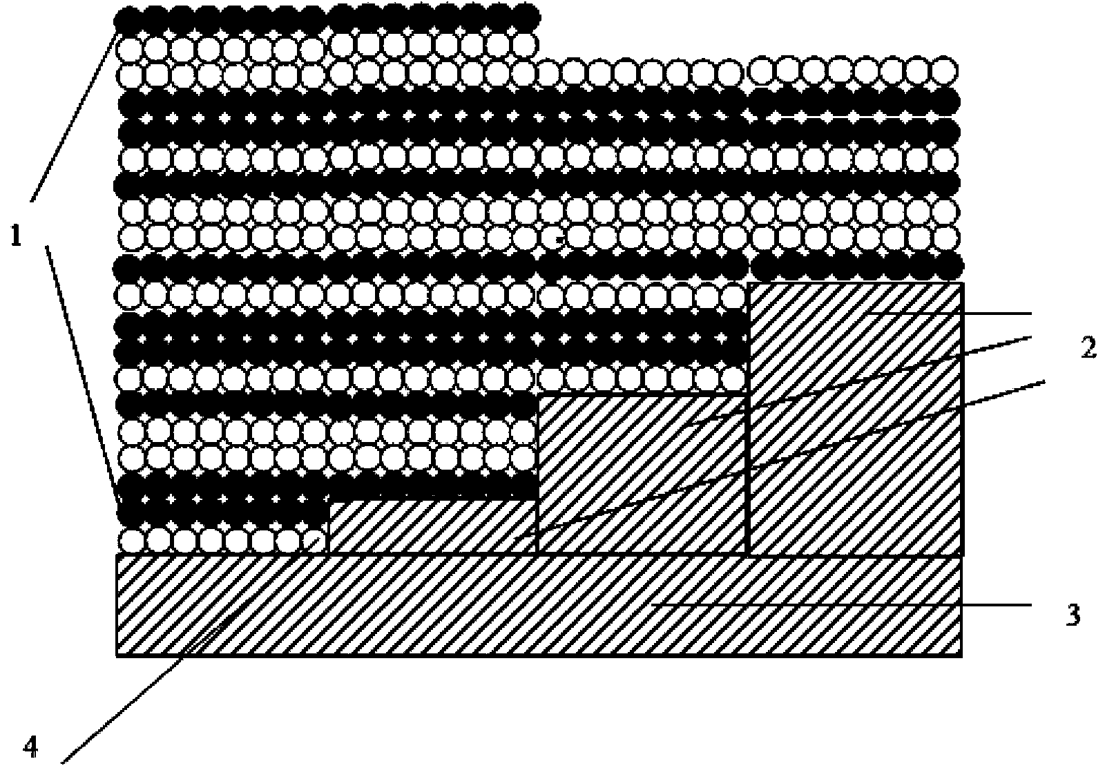
[0038] Install the winding tooling on the four-layer stepped ring skeleton, and wind the polarization-maintaining optical fiber according to the eight-pole symmetrical winding method:

[0039] Take a moderately long polarization-maintaining optical fiber and wind it from the midpoint of the entire optical fiber. The winding starting point 4 is located at figure 1 The boundary between the lowest two steps of the ring frame shown; the optical fiber on the side of the midpoint rotates clockwise to the left edge of the ring frame until the leftmost edge of the lower first step, completing the first step Winding of the first layer of optical fiber; the optical fiber on the other side of the midpoint rotates counterclockwise to the left of the ring frame until it reaches the leftmost edge of the first step, completing the winding of the second layer of optical fiber in the first step; continue Wrap the polarization-maintaining fiber so that it forms an anti-quadrupo...


PUM


Abstract

The invention belongs to the technical field of optic fiber gyroscopes, and in particular relates to a preparation method of a sensing ring capable of reducing optic fiber gyroscope temperature drift. The method of the present invention adopts a quadrupole symmetry method and an octupole symmetry method to wind the optical fiber ring. With the method of the present invention, the shupe phase error due to the temperature is inhibited, and the temperature performance of the gyroscope is improved.

Description

technical field [0001] The invention belongs to the technical field of fiber optic gyroscopes, and in particular relates to a method for preparing a sensing ring capable of reducing the temperature drift of the fiber optic gyroscope. Background technique [0002] The fiber optic sensing ring is the core component of the fiber optic gyroscope that uses the Sagnac mechanism to work and is sensitive to the increment of the rotation angle. Since the fiber itself is a very sensitive sensor, it is extremely sensitive to factors such as temperature, magnetic field, and stress. , so the optical fiber sensing loop is inevitably affected by these factors. For a long time, temperature performance has been an important index in the research and engineering application of fiber optic gyroscopes. The ambient temperature will directly and indirectly induce additional phase errors, which are indistinguishable from the phase difference introduced by rotation, resulting in the zero position e...

Claims


Application Information

Patent Timeline
IPC IPC(8): G01C19/72
CPCG01C19/721G01C25/00
Inventor 毕聪志孙国飞徐广海张丽哲吴衍记
Owner BEIJING AUTOMATION CONTROL EQUIP INST
Why Eureka
Try Eureka