Mimic-disconnecting switch testing device for relay protection and control method thereof
A technology for simulating circuit breakers and testing devices, which is applied in the field of simulating circuit breaker testing devices and controls for relay protection, and can solve problems such as unrealistic test time, no circuit breakers, and affecting work efficiency
- Summary
- Abstract
- Description
- Claims
- Application Information
AI Technical Summary
Problems solved by technology
Method used
Image
Examples
Embodiment 1
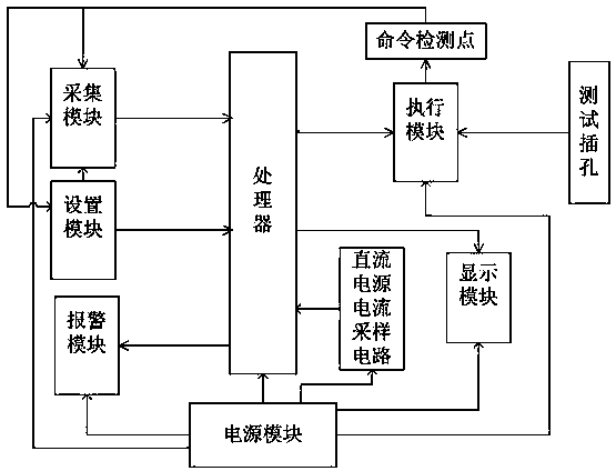
[0127] refer to figure 1 , an analog circuit breaker testing device for relay protection, comprising an acquisition module, a processor, an execution module, a display module, a setting module, an alarm module, a command detection point, a test jack, a DC power supply current sampling circuit and a power module. The test jacks are composed of 107A, 107B, 107C, 137A, 137B, 137C, 237A, 237B, 237C jacks for connecting 107A, 107B, 107C, 137A, 137B, 137C, 237A, 237B, 237C loops, which The corresponding terminals are connected to the corresponding input terminals of the executive module; see Figure 5 , Figure 8 .
[0128] refer to figure 1 , Figure 5 , Figure 8 , the command detection point consists of 107A command detection point KM107A1, 107B command detection point KM107B1, 107C command detection point KM107C1, 137A command detection point KM137A1, 137B command detection point KM137B1, 137C command detection point KM137C1, 237A command detection point KM237A1, 237B Th...
Embodiment 2
[0158] A control method of the described relay protection analog circuit breaker testing device, the specific steps are:
[0159] (1) Power on;
[0160] (2) Initialization: the relays KM3, KM6, KM9, KM7, KM4, and KM10 are in the pull-in state, the relays KM1, KM2, and KM5 are in the release state, and the device is in the off state; the phase A, The opening indicators of phase B and C are on, and the closing indicators of phase A, B and C are off. Read the closing setting time and opening setting time, and the phase A timer, B phase timer and C phase timer are cleared. zero;
[0161] (3) The timer is cleared;
[0162] (4) Detect whether the output current of the DC power supply current detection circuit is greater than 0.5A, if not, turn to step (3); if yes, execute step (5);
[0163] (5) Sampling the signal input of each phase: sampling the magnitude of the current value input by 107A, 107B, 107C, 137A, 137B, 137C, 237A, 237B, and 237C loops; ...
PUM
 Abstract
Description
Claims
Application Information
 - R&D
- Intellectual Property
- Life Sciences
- Materials
- Tech Scout
- Unparalleled Data Quality
- Higher Quality Content
- 60% Fewer Hallucinations
Browse by: Latest US Patents, China's latest patents, Technical Efficacy Thesaurus, Application Domain, Technology Topic, Popular Technical Reports.
© 2025 PatSnap. All rights reserved.Legal|Privacy policy|Modern Slavery Act Transparency Statement|Sitemap|About US| Contact US: help@patsnap.com


