
Antenna structure and wireless communication device using the antenna structure

An antenna structure and antenna technology, applied in the direction of the device that makes the antenna work in different bands at the same time, the antenna support/installation device, the antenna, etc., to achieve the effect of reducing the space volume

Inactive Publication Date: 2018-12-04
SHENZHEN FUTAIHONG PRECISION IND CO LTD +1
View PDF5 Cites 0 Cited by
  • Summary
  • Abstract
  • Description
  • Claims
  • Application Information

AI Technical Summary

Problems solved by technology

On the other hand, the antenna structure is generally more complex, but since the appearance of the antenna module tends to be thinner and miniaturized, the antenna design must also have the characteristics of miniaturization in addition to receiving multiple frequency bands

Method used


Image

  • Antenna structure and wireless communication device using the antenna structure
  • Antenna structure and wireless communication device using the antenna structure

Examples


Embodiment Construction

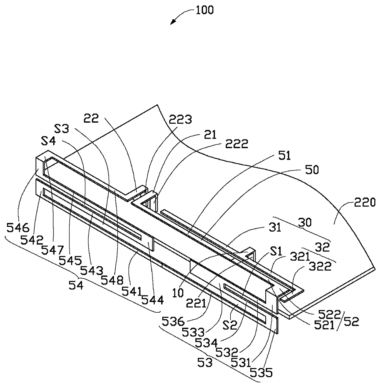
[0013] see figure 1 , the preferred embodiment of the present invention discloses an antenna structure 100, which is applied in wireless communication devices 200 such as mobile phones and tablet computers.

[0014] The wireless communication device 200 includes a circuit board 220 on which a feeding point 221 , a first grounding point 222 and a second grounding point 223 are disposed. The feed-in point 221 is used to feed current into the antenna structure 100 , and the first ground point 222 and the second ground point 223 provide a system ground for the antenna structure 100 . In this embodiment, the antenna structure 100 is suspended from one end of the circuit board 220 .

[0015] The antenna structure 100 includes a feeding terminal 10 , a first ground terminal 21 , a second ground terminal 22 , a first antenna 30 and a second antenna 50 . The feeding end 10 is connected to the feeding point 221 , the first grounding end 21 and the second grounding end 22 are arranged ...


PUM


Abstract

The invention provides an antenna structure which comprises a feed-in end, a first grounding end, a second grounding end, a first antenna and a second antenna. The first antenna comprises a first radiator and a second radiator which are sequentially connected with each other, the first radiator and the second radiator are connected with the feed-in end, the second antenna comprises a first radiation portion, a second radiation portion, a third radiation portion and a fourth radiation portion, the first radiation portion, the second radiation portion, the third radiation portion and the fourth radiation portion are sequentially connected with one another and form a semi-closed ring structure, the first radiation portion and the first radiator are arranged at intervals, the second radiation portion and the second radiator are arranged at intervals, and the first radiation portion and the fourth radiation portion are respectively connected with the first grounding end and the second grounding end. The antenna structure has the advantages that current signals are fed via the first antenna, the first antenna is coupled onto the second antenna, and accordingly wireless signals in various frequency bands can be received and transmitted by the antennas.

Description

technical field [0001] The present invention relates to a wireless communication device and its antenna structure, in particular to a wireless communication device covering multiple frequency bands and its antenna structure. Background technique [0002] In a wireless communication device, the antenna device used to transmit and receive radio waves to transmit and exchange radio data signals is undoubtedly one of the most important components in the wireless communication device. In recent years, the emergence of various communication systems and applications using different operating frequency bands has led to the development of antenna design towards antenna structures covering multiple system frequency bands. In order to ensure that the wireless communication device can perform signal transmission in various wireless communication systems using different operating frequency bands, the antenna device must be capable of transmitting and receiving signals of various frequenc...

Claims


Application Information

Patent Timeline
Patent Type & Authority Patents(China)
IPC IPC(8): H01Q1/36H01Q5/10H01Q21/00H01Q1/22
Inventor 刘耿宏林彦辉
Owner SHENZHEN FUTAIHONG PRECISION IND CO LTD
Learn More