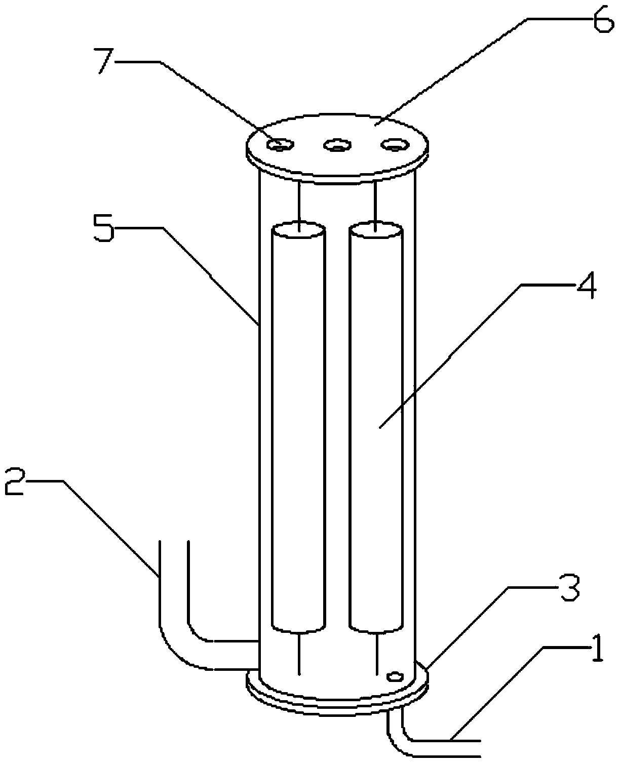
Porous medium defoamer
A porous medium and defoamer technology, applied in the direction of foam dispersion/prevention, can solve the problems of complex operation, high equipment requirements, high energy consumption, etc., and achieve the effect of low energy consumption, convenient operation, and improved defoaming efficiency
- Summary
- Abstract
- Description
- Claims
- Application Information
AI Technical Summary
Problems solved by technology
Method used
Image
Examples
Embodiment 1
[0022] The material system used is an aqueous solution of sodium lauryl sulfate, the liquid hold-up rate of the formed foam is 1%, the half-life of the foam is 30min (measured by GB / T7462-94) and the superficial flow velocity of the foam is 3.5mm / s, and the foam consists of a foam The inlet pipe enters the defoamer, and the foam flows from bottom to top. The cylinder height-to-diameter ratio of the porous medium defoamer is 1, the porous medium column height-to-diameter ratio is 10, and the number of porous medium columns placed on the unit cross-sectional area of the cylinder is 40 / m 2 , and arranged in an equilateral triangle, the density of polyurethane foam is 45kg / m 3 And the pore diameter is 300um, and the distance from the bottom edge of the foam inlet pipe to the bottom cover is 100mm.
[0023] Under the same system conditions, an empty cylinder without components of the same size is used as the defoamer. After 6 minutes, the foam overflows the defoamer; a stirring ...
Embodiment 2
[0025] The substance used is an aqueous solution of sodium lauryl sulfate, the liquid hold-up rate of the formed foam is 3%, the half-life of the foam is 60min (measured by GB / T7462-94) and the superficial flow velocity of the foam is 7mm / s, and the foam enters from the foam The pipe enters the defoamer, and the foam flows from bottom to top. The cylinder height-to-diameter ratio of the porous medium defoamer is 5, the porous medium column height-to-diameter ratio is 50, and the number of porous medium columns placed on the unit cross-sectional area of the cylinder is 200 / m 2 , and arranged in an equilateral triangle, the density of polyurethane foam is 45kg / m 3 And the pore diameter is 300um, the distance from the bottom edge of the foam inlet pipe to the bottom cover is 200mm.
[0026] Under the same system conditions, an empty cylinder without components of the same size is used as a defoamer. After 5 minutes, the foam overflows the defoamer; a stirring defoamer with a r...
Embodiment 3
[0028] The material system used is sodium lauryl sulfate aqueous solution, the liquid hold-up rate of the formed foam is 5%, the half-life of the foam is 120min (measured by GB / T7462-94) and the superficial flow velocity of the foam is 10mm / s, and the foam enters from the foam The pipe enters the defoamer, and the foam flows from bottom to top. The cylinder height-to-diameter ratio of the porous medium defoamer is 10, the porous medium column height-to-diameter ratio is 80, and the number of porous medium columns placed on the unit cross-sectional area of the cylinder is 1200 / m 2 , and arranged in an equilateral triangle, the density of polyurethane foam is 45kg / m 3 And the pore diameter is 300um, the distance from the bottom edge of the foam inlet pipe to the bottom cover is 300mm.
[0029] Under the same system conditions, an empty cylinder without components of the same size is used as the defoamer. After 4 minutes, the foam overflows the defoamer; a stirring defoamer wi...
PUM
| Property | Measurement | Unit |
|---|---|---|
| density | aaaaa | aaaaa |
| height | aaaaa | aaaaa |
| density | aaaaa | aaaaa |
Abstract
Description
Claims
Application Information
 - R&D
- Intellectual Property
- Life Sciences
- Materials
- Tech Scout
- Unparalleled Data Quality
- Higher Quality Content
- 60% Fewer Hallucinations
Browse by: Latest US Patents, China's latest patents, Technical Efficacy Thesaurus, Application Domain, Technology Topic, Popular Technical Reports.
© 2025 PatSnap. All rights reserved.Legal|Privacy policy|Modern Slavery Act Transparency Statement|Sitemap|About US| Contact US: help@patsnap.com

