Lathe sliding box

A technology of sliding crate and lathe, which is applied in the field of lathe crate and lathe, and can solve problems such as limitations

Active Publication Date: 2015-01-07
YANGZHOU SUPER MASCH TOOL CO LTD
View PDF11 Cites 8 Cited by
  • Summary
  • Abstract
  • Description
  • Claims
  • Application Information

AI Technical Summary

Problems solved by technology

Both types of overload pr

Method used


Image

  • Lathe sliding box
  • Lathe sliding box
  • Lathe sliding box

Examples


Embodiment Construction

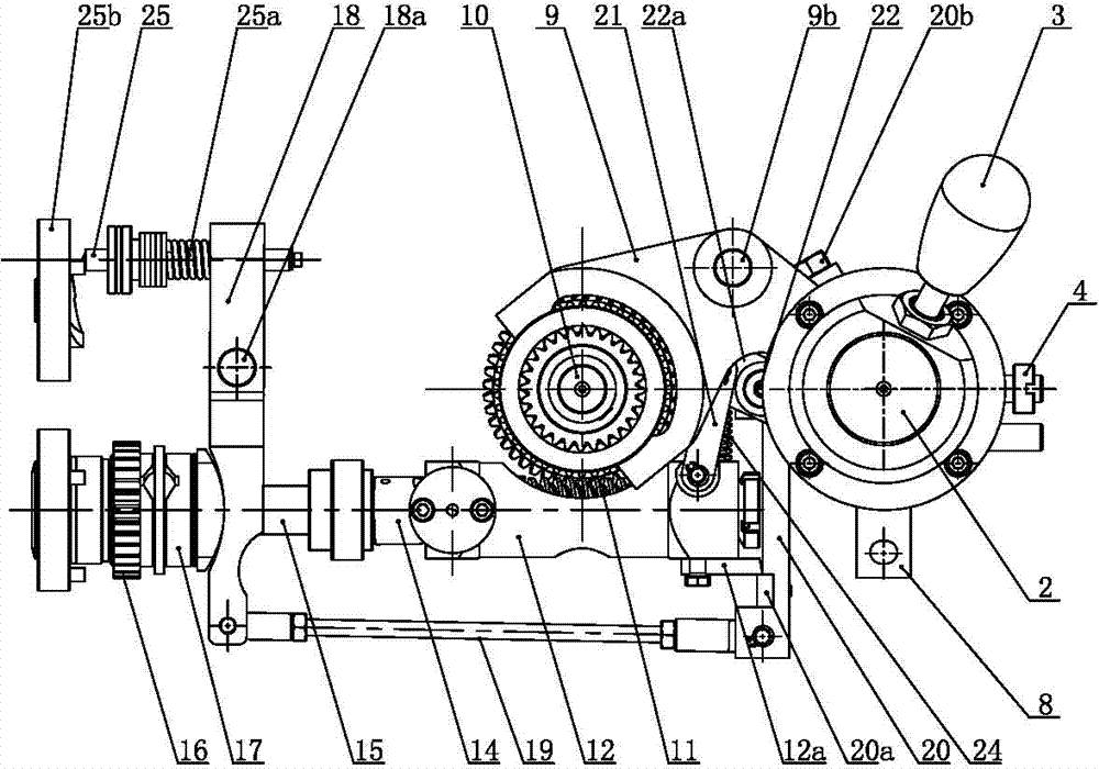
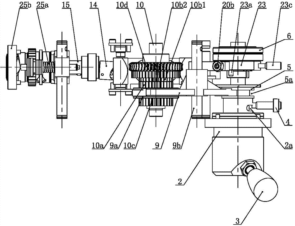
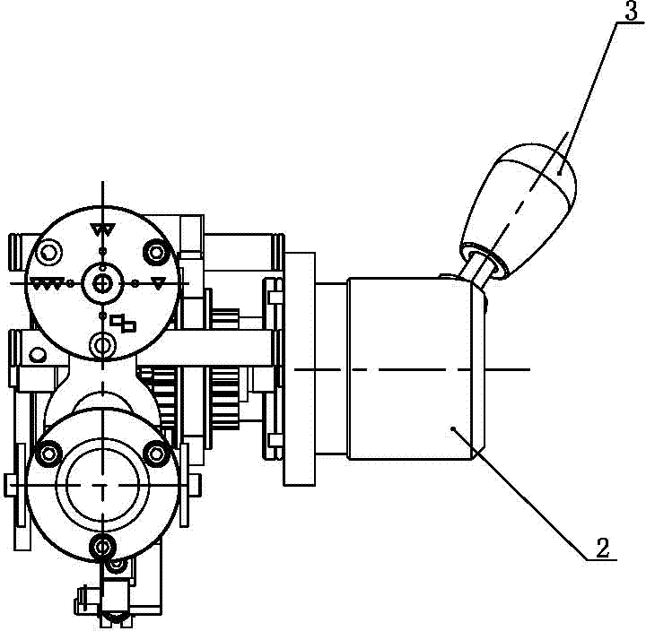
[0056] Such as Figure 1 to Figure 10 As shown, the lathe slide box of the present invention includes a box body, on which a wheel shaft 10 is fixedly installed, and an intermediate gear 10a is fixedly installed in the middle part of the wheel shaft 10, and the front and rear sides of the intermediate gear 10a are equipped with longitudinal tool gears 10c and transverse The cutting gear 10b1, the transverse cutting gear 10b1 and the longitudinal cutting gear 10c can rotate on the axle 10 respectively, and the intermediate gear 10a, the horizontal cutting gear 10b1 and the longitudinal cutting gear 10c can be meshed with the inner ring gear 9a respectively.

[0057] The lathe slide box also includes a joystick shaft 2, the middle part of the joystick shaft 2 is located in the joystick seat 1 and can rotate or slide back and forth in the joystick seat 1, the axis of the joystick shaft 2 is parallel to the axis of the wheel shaft 10, One end of the joystick shaft 2 is installed w...


PUM


Abstract

The invention relates to a lathe sliding box; a transverse knife feeding gear and a longitudinal knife feeding gear are installed on front and rear sides of a middle gear on a wheel shaft; the middle gear, the transverse knife feeding gear and the longitudinal knife feeding gear are respectively engaged with an annular gear; a control handle shaft is parallel to the wheel shaft; a handle capable of driving the control handle shaft to rotate or slide forwards and backwards is installed on the control handle shaft; the annular gear is rotationally connected to one end of a sliding link rod, and the middle part of the sliding link rod is installed on a sliding link rod shaft that is parallel to the control handle shaft; a sliding link rod driving plate is fixedly installed on the control handle shaft and provided with a sliding link rod slot extending along the circumference, and the other end of the sliding link rod is inserted into the sliding link rod slot. A concave arc cam is installed on the control handle shaft, the rear end face of the concave arc cam is provided with a concave arc groove in which a link rod pin is inserted, and the outer end of the link rod pin is hinged to the upper end of a half nuts control link rod. According to the sliding box, interlocking of the transverse knife feeding gear, the longitudinal knife feeding gear and the half nuts is achieved by the control handle.

Description

technical field [0001] The invention relates to a lathe, in particular to a lathe slide box, which belongs to the technical field of machine tools. Background technique [0002] The slide box is an important part of the lathe. It cooperates with the feed box to allow the tool post to perform thread cutting, vertical and horizontal feed and rapid movement. The sliding crate includes vertical and horizontal motorized feed and fast-moving operating mechanism, split nut mechanism, interlock mechanism and overload protection device. [0003] The wheel shaft is fixedly installed on the sliding crate box, and the middle part of the wheel shaft is fixedly installed with an intermediate gear. The front and rear sides of the intermediate gear are equipped with a horizontal feed gear and a longitudinal feed gear. Rotating on the wheel shaft, the intermediate gear, the transverse feed gear and the longitudinal feed gear can mesh with the inner ring gear respectively. When the inner ri...

Claims


Application Information

Patent Timeline
IPC IPC(8): B23B21/00B23Q1/25B23Q5/34B23Q5/58
CPCB23Q1/25B23Q5/34B23Q5/58
Inventor 卢华国韩进孔庆善
Owner YANGZHOU SUPER MASCH TOOL CO LTD
Why Eureka
Try Eureka