Flat-end milling cutter

A flat end mill and head technology, applied in the field of metal cutting processing, can solve the problems of restricting the cutting performance and service life of the tool, different degrees of chip deformation, and chipping of the tool tip, and improve the sudden change of the working rake angle. , the effect of weakening the mutual interference and smooth transition

Active Publication Date: 2015-01-07
ZHUZHOU CEMENTED CARBIDE CUTTING TOOLS CO LTD
View PDF6 Cites 3 Cited by
  • Summary
  • Abstract
  • Description
  • Claims
  • Application Information

AI Technical Summary

Problems solved by technology

[0004] Although the use of the "end-tooth-enhanced wide" tip can enhance the strength of the flat-end milling cutter tip and improve the cutting performance of the tool, there are still certain defects in this tool tip. The rake surface at the tooth reinforcement wide surface 10 is actually the end tooth rake surface 7, and the spiral groove rake surface 9 forms a slope with a large angle at the intersection with the plane. The existence of this slope at least affects the cutting performance of the tool. There are two effects: First, looking from the normal direction of the flank 5 of the peripheral edge, the original spiral edge line at the tip is destroyed by the end tooth reinforcement wide surface 10, forming a gap between the "end tooth reinforcement width" and the peripheral edge 4. The sharper inflection point 14, the actual helix angle and the radial rake angle of the tool cutting edge on both sides of the inflection point 14 suddenly change
Since the helix angle at the "enhanced width of the end teeth" decreases sharply to be close to the value of the axial rake angle of the end teeth, and at the same time the radial rake angle also decreases sharply from a positive value to zero or even a negative value. The shear angle and outflow angle of the chips formed by the side cutting edge cutting are very different, and the degree of chip deformation is greatly different, and the chips interfere with each other when they flow out, which affects the stability of the cutting; The intersection of the 9 phases on the rake face of the groove will bear a relatively large impact, and stress concentration will occur at the inflection point. When heavy-duty or high-speed cutting is performed, the tool tip is prone to chipping or increased wear, which is serious. Restricts the improvement of the cutting performance and service life of the tool

Method used


Image

  • Flat-end milling cutter
  • Flat-end milling cutter
  • Flat-end milling cutter

Examples


Embodiment Construction

[0028] The present invention will be further described in detail below in conjunction with the accompanying drawings and specific embodiments.

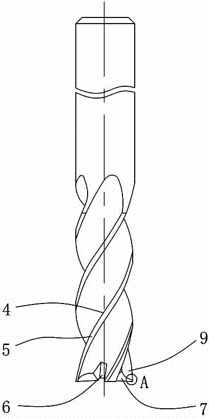
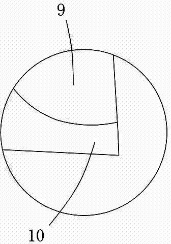
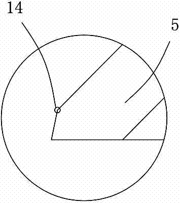
[0029] Figure 4 to Figure 8 An embodiment of the flat end mill of the present invention is shown, the flat end mill includes a handle part 1 and a cutting part 2, and the cutting part 2 is provided with more than two blades extending from the cutting head to the handle part 1. The spiral chip flute 3, the wall surface of the spiral chip flute 3 facing the cutting rotation direction is the spiral flute rake face 9, the cutting part 2 is opposite to the processed surface of the workpiece and connected with the spiral flute rake face 9 and distributed along the circumferential direction The outer surface of the outer surface is the peripheral flank flank 5, and the cutting head of the cutting part 2 is formed with a groove-shaped end-tooth chip flute 6 extending from the spiral chip flute 3 to the inside. The blade flanks 5 are connect...


PUM


Abstract

The invention discloses a flat-end milling cutter. The flat-end milling cutter comprises a cutter handle part and a cutting part, wherein the cutting part is provided with more than two spiral chip discharge grooves extending from the cutting head part to the cutter handle part; the wall surfaces, which face the cutting rotation direction, of the spiral chip discharge grooves are spiral groove front cutter surfaces; the outer surface of the cutting part, which is opposite to a processed surface, and is connected with front cutter surfaces of the spiral grooves, and distributed along the periphery, is an outer periphery blade rear cutter surface; the cutting head part of the cutting part is provided with a groove-shaped end tooth chip accommodating groove extending internally from the spiral chip discharge grooves; the wall surface in the end tooth chip accommodating groove, which is connected with the outer peripheral blade rear cutter surface and faces the rotation direction of the flat-end milling cutter, is an end tooth front cutter surface; a small partial curved surface on the end tooth front cutter surface, which is close to a blade line formed by the intersection of the end tooth front cutter surface and the peripheral blade rear cutter surface, is an end tooth reinforcing wide surface; a circular arc transition curved surface is arranged between the end tooth reinforcing wide surface and the spiral groove front cutter surface, and is connected with the end tooth reinforcing wide surface and the spiral groove front cutter surface. The flat-end milling cutter has the advantages of high cutter point strength, good cutting performance, long service life and the like.

Description

technical field [0001] The invention relates to the field of metal cutting, in particular to a flat end mill. Background technique [0002] During the cutting process, for flat end mills, the main failure form is cutting edge wear or chipping, especially the tool tip, which often causes problems first during the cutting process. Once the tip of the milling cutter is severely worn or chipped, the instantaneous cutting force will suddenly increase, the tool cannot perform normal and stable cutting, and may even cause serious consequences of chipping or fracture of the cutting edge at the bottom of the tool. Therefore, for flat end mills, To achieve the goal of improving the cutting performance and service life of the tool by improving the tool structure, the key is to increase the strength of the tip of the milling cutter to improve the wear resistance and chipping resistance of the tool tip. [0003] According to the shape of the cutting edge, flat end mills in the prior art...

Claims


Application Information

Patent Timeline
Patent Type & Authority Applications(China)
IPC IPC(8): B23C5/10
CPCB23C5/1081B23C2210/0442B23C2210/40
Inventor 曾滔邱润福方曙璋左小陈
Owner ZHUZHOU CEMENTED CARBIDE CUTTING TOOLS CO LTD
Why Eureka
Try Eureka