
Rapid induced flow completion pipe column for subsurface nitrogen making gas well

A completion string and nitrogen technology, applied in wellbore/well components, drill pipe, casing, etc., can solve the problems of complex operation procedures, high risks, low efficiency, etc., and achieve simple operation procedures, less operation equipment, Efficient effect

Inactive Publication Date: 2015-01-07
CHINA NAT OFFSHORE OIL CORP +1
View PDF11 Cites 3 Cited by
  • Summary
  • Abstract
  • Description
  • Claims
  • Application Information

AI Technical Summary

Problems solved by technology

The multi-stage gas-lift string injection technology is limited by the air-tightness of the gas-lift valve in the long-term production process, and at the same time has poor flexibility, so it is rarely used at present
[0003] At present, the common problem existing in the gas well completion string is that the string itself does not have the function of inducing blowout, and needs to induce blowout separately. Low efficiency, high cost, high risk
[0004] At present, there is no gas well rapid induced blowout completion string, the following are the retrieved related patents

Method used


Image

  • Rapid induced flow completion pipe column for subsurface nitrogen making gas well
  • Rapid induced flow completion pipe column for subsurface nitrogen making gas well

Examples


Embodiment Construction

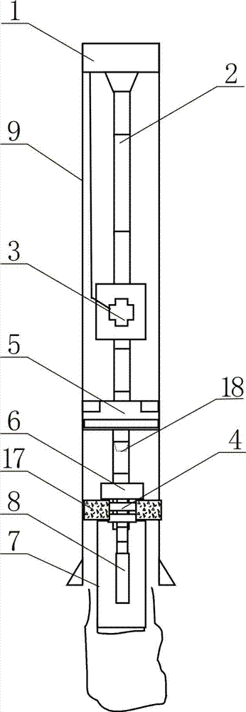
[0020] Such as figure 1 , 2 As shown, the rapid blowout induction completion string of the downhole nitrogen gas well is mainly composed of tubing hanging 1, tubing 2, downhole safety valve 3, production packer 5, insertion positioning seal 6, blind pipe 7, downhole nitrogen generating blowout induction device 8 and Mandrel 18 Composition, wherein, the upper end of the oil pipe 2 is suspended in the oil well 9 through the oil pipe hanger 1, the downhole safety valve 3 and the production packer 5 are respectively arranged on the oil pipe 2, and the lower end of the oil pipe 2 is inserted into the positioning seal 6 and the blind pipe 7 connection, the insertion positioning seal 6 is inserted into the sealing cylinder of the sand control packer 17 in the oil well 9, and the downhole nitrogen generating blowout device 8 is arranged in the blind pipe 7. A sealing ring 4 is provided between the insertion positioning seal 6 and the sealing cylinder of the sand control packer 17; ...


PUM


Abstract

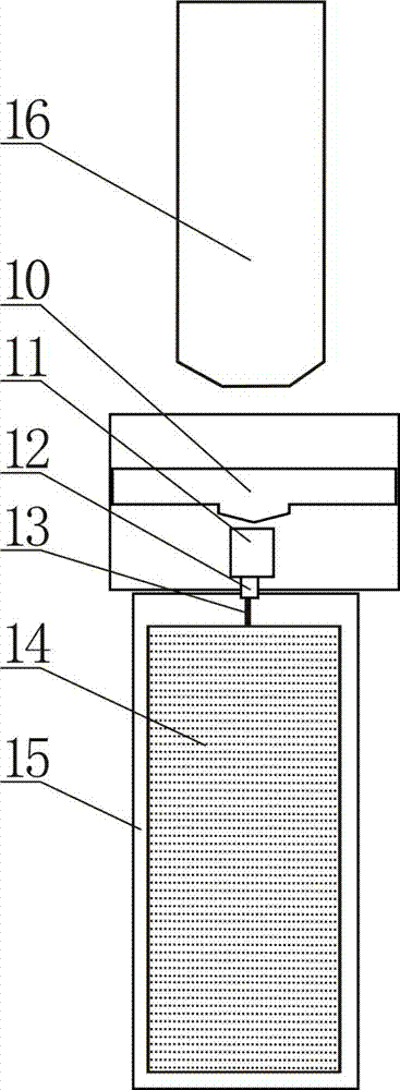
The invention discloses a rapid induced flow completion pipe column for a subsurface nitrogen making gas well. The rapid induced flow completion pipe column for the subsurface nitrogen making gas well is mainly formed by a mandrel hanger, an oil tube, a subsurface safety valve, a production packer, a working barrel, an insertion positioning seal, a blind tube and a subsurface nitrogen induced flow device; the upper end of the oil tube hangs inside an oil well through the mandrel hanger; the subsurface safety valve, the production packer and the working barrel are respectively arranged on the oil tube; the lower end of the oil tube is connected with the blind tube through the insertion positioning seal; the insertion positioning seal is inserted inside a sealing cylinder of a sand control packer inside the oil well; the subsurface nitrogen making induced flow device is inserted to the blind tube; the subsurface nitrogen making induced flow device is mainly formed by an ignition head, an exploder, a booster tube, a detonating cord, a gas generating agent and an outer casing; the ignition head is arranged at the top of the exploder; the exploder is connected with the detonating cord through the booster tube; the outer casing is full of the gas generating agent which is connected with the detonating cord. According to the above structural form, the rapid induced flow completion pipe column for the subsurface nitrogen making gas well has the advantages of being few in induced flow operation equipment, simple in operation process, high in efficiency, low in cost and stable and reliable.

Description

technical field [0001] The invention relates to a blowout-inducing and completion pipe string, in particular to a fast-induced blowout completion pipe string for an underground nitrogen gas well. Background technique [0002] At present, offshore gas wells are usually run into completion strings first, and then blowout induction is performed separately, and the completion string itself does not have the function of induction blowout. Coiled tubing nitrogen injection is usually used to induce blowout in offshore gas wells. This technology needs to connect nitrogen (liquid nitrogen) equipment and coiled tubing equipment on the drilling platform. There are many operating equipment, complex operating procedures, long operating time, high operating costs, and relatively high risks. In addition, there are small-diameter tube nitrogen induced injection technology and multi-stage gas lift column induced injection technology. The advantages and disadvantages of the small-diameter p...

Claims


Application Information

Patent Timeline
IPC IPC(8): E21B43/16E21B17/00
CPCE21B43/168E21B33/12
Inventor 许发宾黄凯文曾春珉梁继文张崇黄亮余意刘贤玉徐靖
Owner CHINA NAT OFFSHORE OIL CORP
Learn More