
Windward collection device, engine with windward collection device, and windward distribution method

A collection device and engine technology, applied to engine components, machine/engine, engine cooling, etc., can solve the problems of low air flow rate, waste of resources, and inability to fully discharge waste, so as to improve power output and reduce NOx generation Effect

Inactive Publication Date: 2015-01-07
HITACHI AUTOMOTIVE SYST SUZHOU
View PDF5 Cites 4 Cited by
  • Summary
  • Abstract
  • Description
  • Claims
  • Application Information

AI Technical Summary

Problems solved by technology

[0006] However, the fan in Patent Document 1 is the same as the fan of an outdoor unit of a general air conditioner, and the flow rate of the air passing through the fan is low, so there is a technical problem that the waste in the engine cannot be fully discharged.
That is to say, although the upwind has been partially utilized in Patent Document 1, the upwind with a strong thrust has not been effectively utilized, and there is still a waste of resources

Method used


Image

  • Windward collection device, engine with windward collection device, and windward distribution method
  • Windward collection device, engine with windward collection device, and windward distribution method
  • Windward collection device, engine with windward collection device, and windward distribution method

Examples


Embodiment Construction

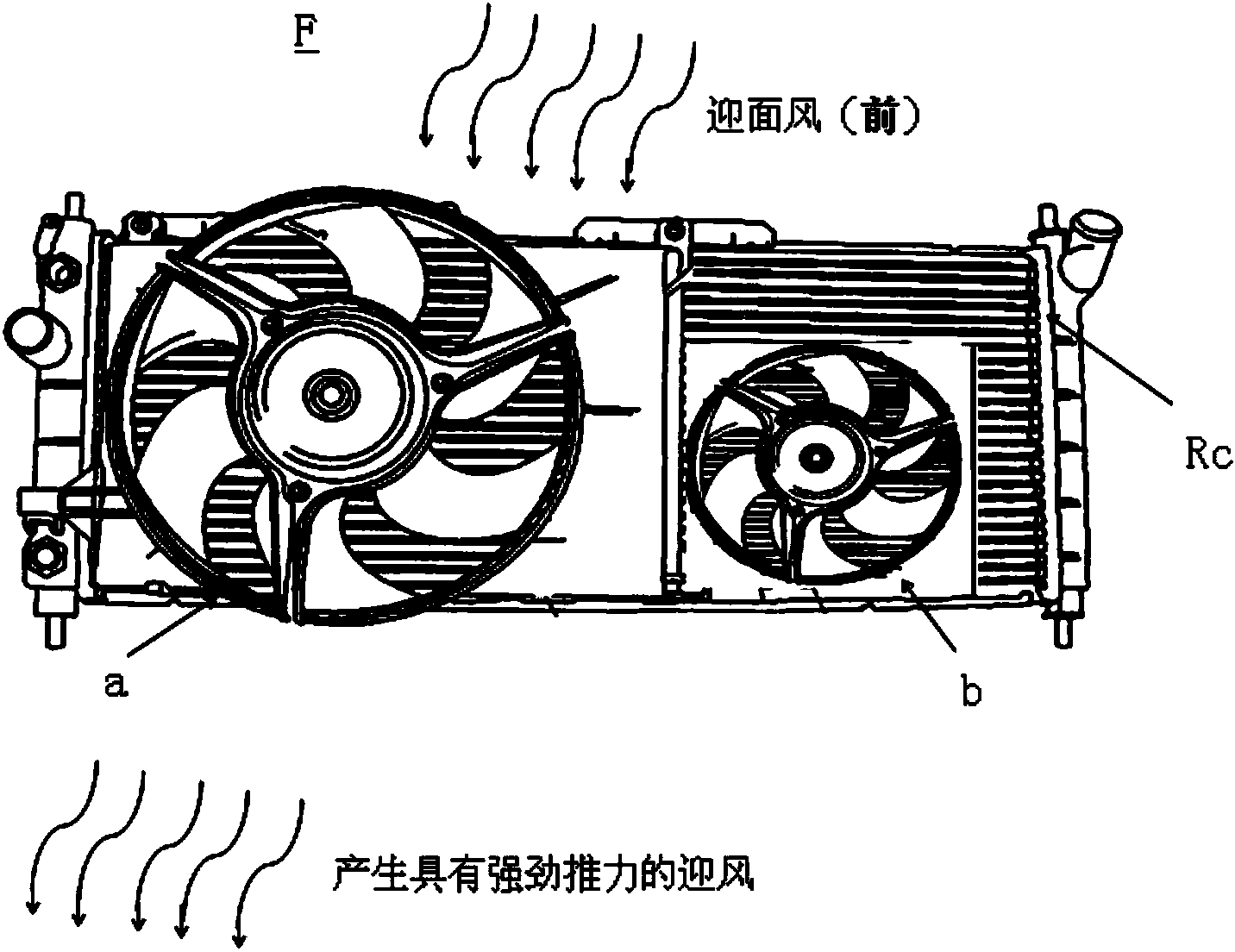
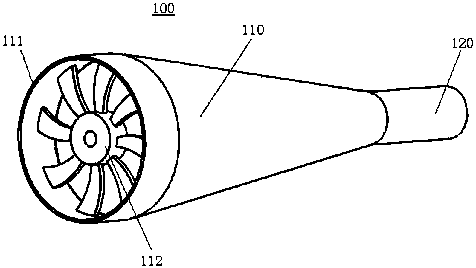
[0035] Below, refer to figure 1 and figure 2 , a perspective view of the windward collecting device of the present invention.

[0036] figure 1 It shows the structure of the cooling fan F used in connection with the windward collector 100 which concerns on embodiment of this invention.

[0037] exist figure 1 Among them, the inner side of the paper is the windward side, and the outer side of the paper opposite to the windward side is the leeward side.

[0038] Such as figure 1 As shown, the cooling fan F includes a high-speed fan a, a low-speed fan b, and a radiator core Rc. The radiator core Rc is located on the windward side of the high-speed fan a and the low-speed fan b.

[0039] The high-speed fan a and the low-speed fan b of the cooling fan F are axial flow fans, and the cooling fan F is used to increase the air velocity flowing through the radiator core Rc, increase the heat dissipation effect, and accelerate the cooling of water.

[0040] When the vehicle is ru...


PUM

PropertyMeasurementUnit
Diameteraaaaaaaaaa

Abstract

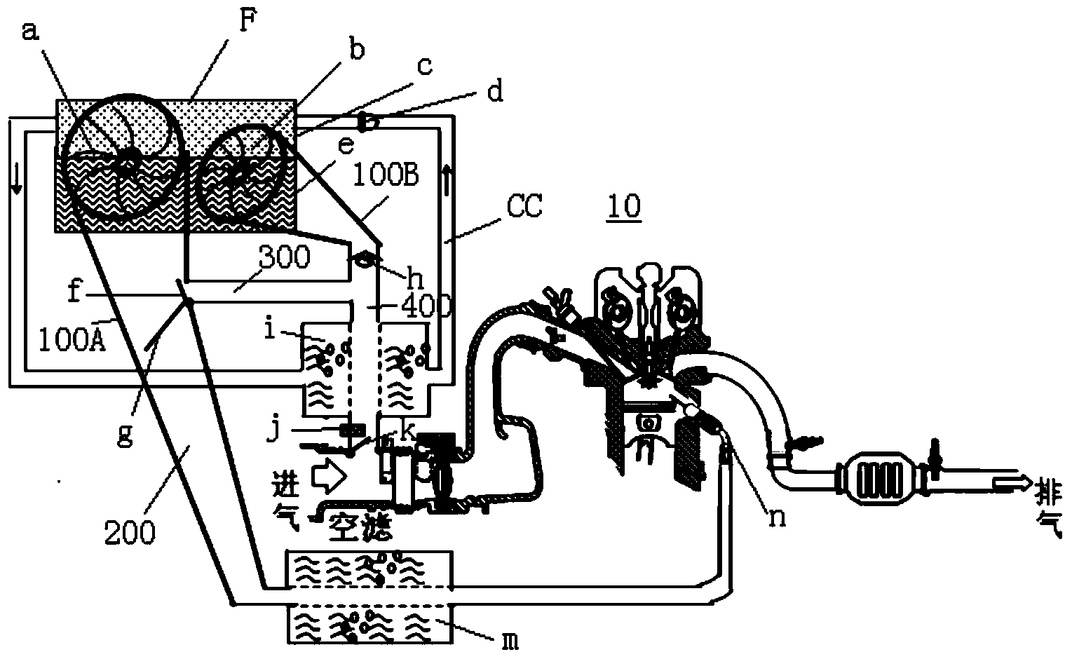
A windward collection device, an engine with the windward collection device, and a windward distribution method can sufficiently and effectively use windward after cooling of a radiator and can reasonably distribute the collected windward according to the operation condition of the engine. The windward collection device (100) is connected with a cooling fan (F) of a vehicle and is characterized by being horn-trumpet-shaped and comprising a collection fan portion (110) and a connection portion (120). A fan (112) is formed on one portion (111) of the collection fan portion (110) close to the windward side, and the portion (111) is connected with the wind outlet side of the cooling fan (F). One end of the connection portion (120) is connected with one portion of the collection fan portion (110) close to the leeward side, and the other end of the connection portion (120) is communicated with an air inlet port and / or a high-pressure nozzle (n) of the engine through a connection pipe.

Description

technical field [0001] The present invention relates to a windward collection device, an engine including the same, and a windward delivery method, and more specifically, to a windward collection for cooling a radiator by the windward (frontal wind) when the vehicle is running. A device, an engine including the device, and a method of upwind delivery. Background technique [0002] The cooling fan is a very important part of the cooling system of the vehicle. It can adjust the cooling air volume at any time according to the water temperature of the engine to ensure that the engine runs at the most favorable temperature. [0003] Conventionally, when the cooling fan is in operation, the front wind (head wind) when the vehicle is running is sucked from the shutter of the vehicle, and the radiator is cooled by the wind, thereby improving the cooling effect of the wind on the radiator. [0004] However, the windward with strong thrust after blowing the radiator is not effectivel...

Claims


Application Information

Patent Timeline
IPC IPC(8): F01P11/10
CPCF01P5/02F01P11/10F01P2005/025
Inventor 丁青松
Owner HITACHI AUTOMOTIVE SYST SUZHOU
Learn More