Method and system for diagnosing fault of clutch control failure

A technology for clutch control and fault diagnosis, applied in transmission control, components with teeth, belts/chains/gears, etc., can solve problems such as inability to determine or accurately determine whether one or two solenoid valves are faulty

Active Publication Date: 2015-01-07
WEICHAI POWER CO LTD
View PDF5 Cites 15 Cited by
  • Summary
  • Abstract
  • Description
  • Claims
  • Application Information

AI Technical Summary

Problems solved by technology

Moreover, the judged clutch failure is only a large category of solenoid valve or clutch booster cylinder failure, and it cannot be judged whether the two solenoid valves are faulty or only one of the solenoid valves is faulty when the clutch is separated or co

Method used


Image

  • Method and system for diagnosing fault of clutch control failure
  • Method and system for diagnosing fault of clutch control failure
  • Method and system for diagnosing fault of clutch control failure

Examples


Embodiment 1

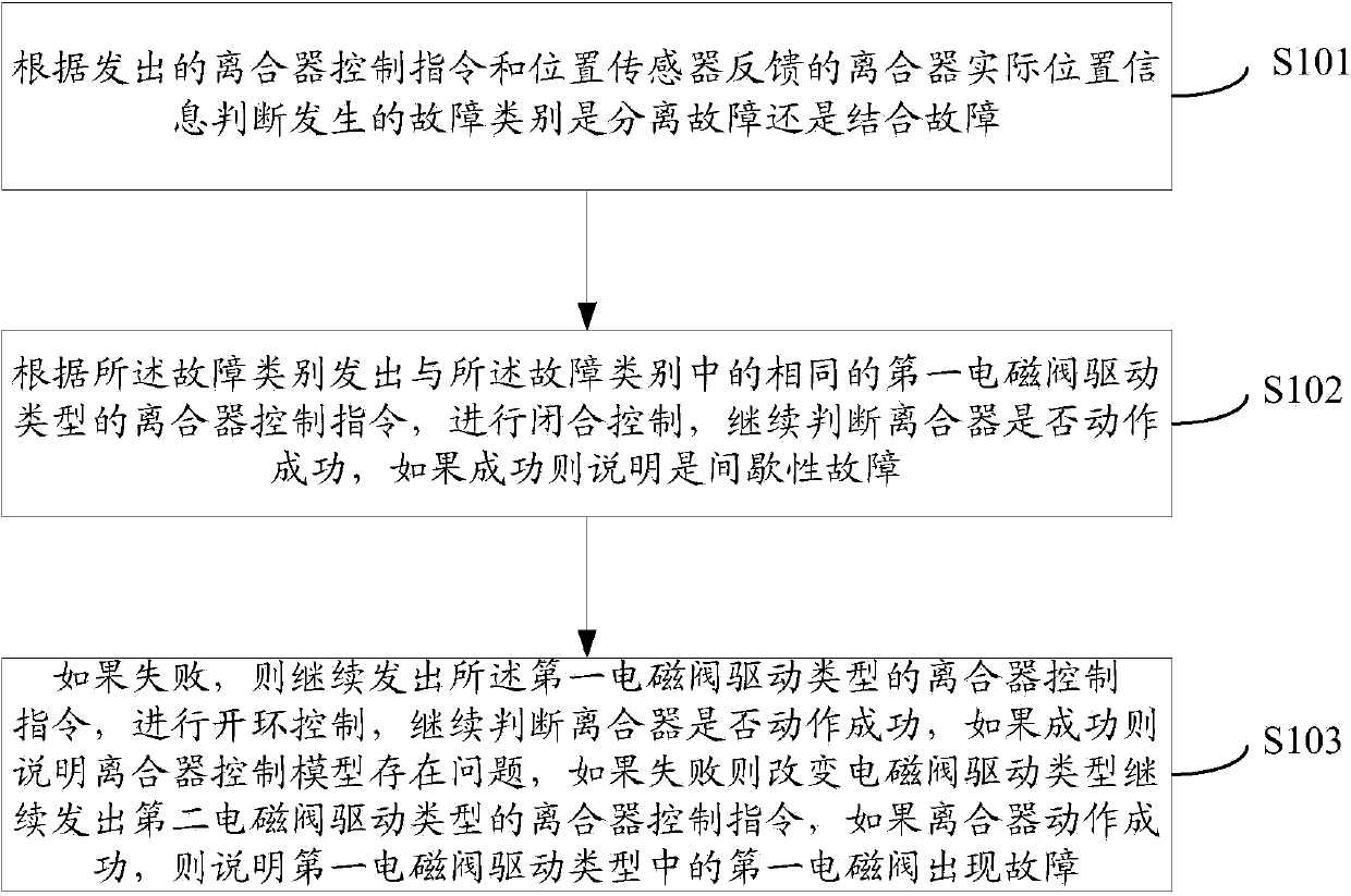
[0061] see figure 1 , which is a flow chart of Embodiment 1 of the fault diagnosis method for clutch control failure provided by the present invention.

[0062] This embodiment provides a fault diagnosis method for clutch control failure, including the following steps:

[0063] S101: According to the issued clutch control command and the actual position information of the clutch fed back by the position sensor, it is judged whether the type of fault occurred is a separation fault or a coupling fault;

[0064] Firstly, when controlling the action of the clutch, an action control command will be sent to the clutch, for example, it can be a separation and closing control command driven by a slow split valve. However, the clutch may break down and the control command is not executed. In this way, the actual position information of the clutch fed back by the position sensor can be used to judge whether the clutch is broken down. Moreover, the type of fault in the clutch can be ju...

Embodiment 2

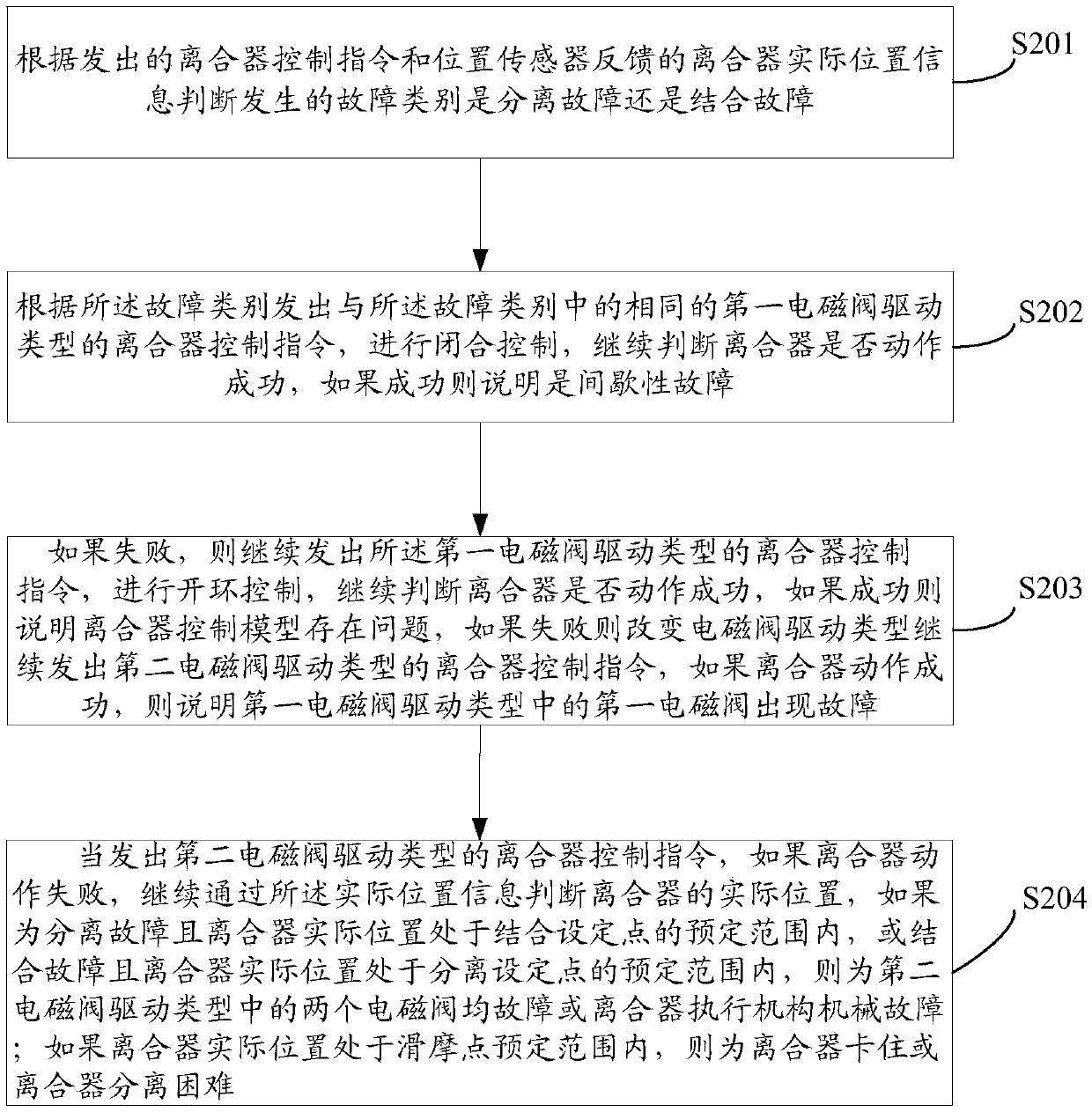
[0074] see figure 2 , which is a flow chart of Embodiment 2 of the fault diagnosis method for clutch control failure provided by the present invention.

[0075] The difference between method embodiment two and method embodiment one is that the following steps are added:

[0076] S204: When the clutch control command of the second electromagnetic valve driving type is issued, if the clutch action fails, continue to judge the actual position of the clutch through the actual position information, if it is a separation failure and the actual position of the clutch is within the predetermined range of the engagement set point , or combined failure and the actual position of the clutch is within the predetermined range of the disengagement set point, then both solenoid valves in the second solenoid valve drive type are faulty or the clutch actuator is mechanically faulty; if the actual clutch position is at the predetermined slip point If it is within the range, the clutch is stuc...

Embodiment 3

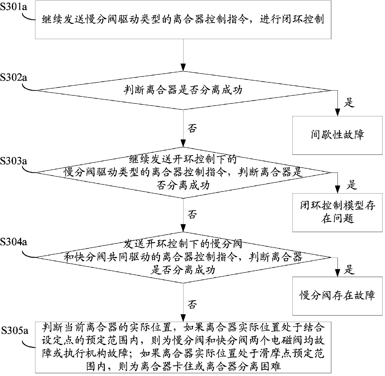
[0088] see Figure 3a , which is a flow chart of Embodiment 3 of the fault diagnosis method for clutch control failure provided by the present invention.

[0089] In this embodiment, the independent drive of the slow branch valve is taken as an example for introduction.

[0090] S301a: continue to send the clutch control command of the slow valve drive type to perform closed-loop control;

[0091] S302a: Judging whether the clutch disengagement is successful, if successful, it means an intermittent fault; if it fails, execute S303a;

[0092] S303a: continue to send the clutch control command of the slow opening valve drive type under open-loop control, and judge whether the clutch is separated successfully. If successful, it means that there is a problem with the closed-loop control model; if it fails, execute S304a;

[0093] S304a: Send a clutch control command jointly driven by the slow opening valve and the fast opening valve under open-loop control, and judge whether the...


PUM


Abstract

The invention provides a method and system for diagnosing a fault of a clutch control failure. The method comprises the steps that whether a fault category is a disengagement fault or an engagement fault is judged according to a sent clutch control instruction and clutch actual position information fed back by a position sensor; a clutch control instruction of the same first electromagnetic valve driving type in the failure category is sent out according to the fault category, closed-loop control is carried out, an operator continues to judge whether a clutch successfully acts or not, and if the clutch successfully acts, an intermittent fault happens; if the clutch does not successfully act, the operator continues to send out the clutch control instruction of the first electromagnetic valve drive type, open-loop control is carried out, and the operator continues to judge whether the clutch successfully acts; if the clutch successfully acts, problems exist in a control model of a clutch; if the clutch does not successfully act, the electromagnetic valve drive type is changed, the operator continues to send out a clutch control instruction of a second electromagnetic valve drive type, and if the clutch successfully acts, a first electromagnetic valve in the first electromagnetic valve drive type fails. According to the method and system, the specific type of the fault of the clutch can be accurately judged in detail.

Description

technical field [0001] The invention relates to the technical field of clutch control, in particular to a fault diagnosis method and system for clutch control failure. Background technique [0002] First introduce a few technical terms in this field: [0003] Automatic gearbox: (also known as ATM gearbox) is developed on the basis of mechanical gearbox (manual gearbox), and the automation of shifting action is realized by adding an automatic shift actuator with a controller. [0004] Clutch booster: instead of the action of the driver stepping on the pedal, it provides driving force for the separation and combination of the clutch under the action of the controller. [0005] Solenoid valve: a valve that relies on the electromagnetic force generated by the power supply coil to drive the movable iron core to open and close the disc, and is used to adjust the direction, flow, speed and other parameters of the medium. [0006] Position sensor: In the clutch booster cylinder, t...

Claims


Application Information

Patent Timeline
IPC IPC(8): F16H61/12
CPCF16H61/12
Inventor 韩尔樑董英荣何汉清乔运乾段军峰王菁
Owner WEICHAI POWER CO LTD
Why Eureka
Try Eureka