Two-way rotating gas dynamic/static pressure mechanical seal type bird wing-shaped groove structure

A gas dynamic and static pressure, two-way rotation technology, applied in the direction of engine seals, mechanical equipment, engine components, etc., can solve the problems of difficult gas pressure in the tank, dry wear of the end face, and short service life of the seal, so as to improve the opening of the end face Performance and anti-interference ability, reduce the probability of end face wear, and prevent the effect of end face wear

Active Publication Date: 2015-01-07
ZHEJIANG UNIV OF TECH
View PDF13 Cites 4 Cited by
  • Summary
  • Abstract
  • Description
  • Claims
  • Application Information

AI Technical Summary

Problems solved by technology

[0003] The present invention is to overcome the dryness of the end face caused by the untimely introduction of air on the end face, the difficulty in effectively establishing the gas pressure in the groove, the too small opening force of the end face or the untimely opening of most of the existing gas-lubricated non-contact mechanical seal technologies. On-site problems such as wear, poor sealing stability or poor anti-interference ability, and short service life of the seal, based on the bionic principle and fluid lubrication theory, and taking the geometry and structure characteristics of the bird's wing as a reference, provide a good opening performance and stability. Good performance, can effectively prevent end face wear during start-up and stop, imitating bird's wing-shaped groove end face seal, can meet the needs of different pressure and different speed operating conditions

Method used


Image

  • Two-way rotating gas dynamic/static pressure mechanical seal type bird wing-shaped groove structure
  • Two-way rotating gas dynamic/static pressure mechanical seal type bird wing-shaped groove structure
  • Two-way rotating gas dynamic/static pressure mechanical seal type bird wing-shaped groove structure

Examples


Embodiment Construction

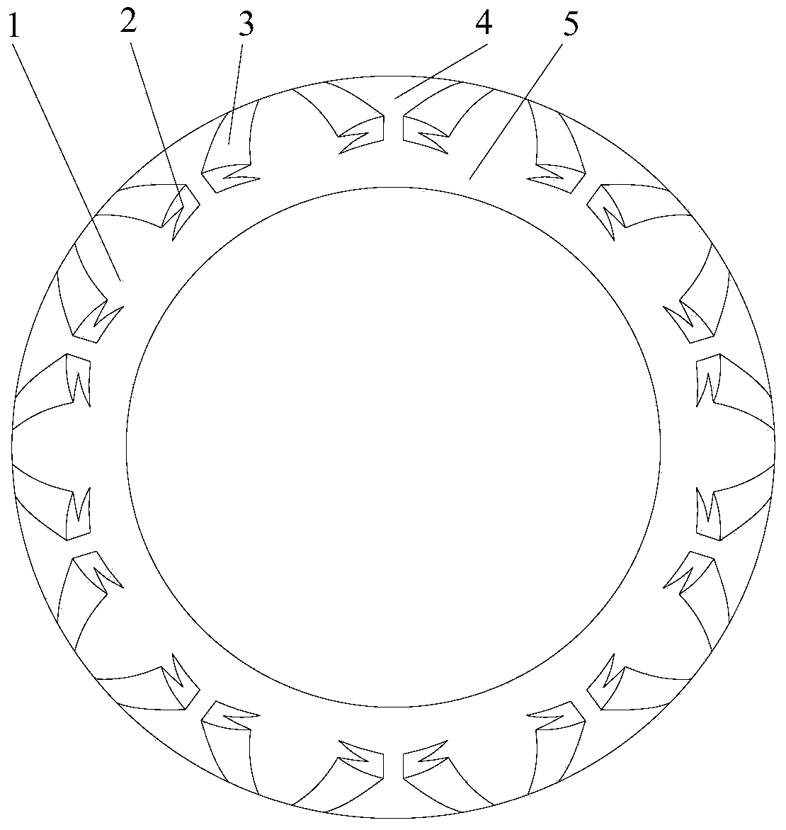
[0023] see Figure 1 to Figure 5 , a bird-wing-shaped groove structure of a bidirectional rotating gas dynamic and static pressure mechanical seal, which includes a dynamic ring and a static ring of the mechanical seal, and is characterized in that: the end face 1 of at least one sealing ring in the dynamic ring and the static ring is set There are a plurality of bird-like wing-like grooves, the bird-like wing-like grooves are shallow grooves on a micron scale, and the bird-like wing-shaped grooves are composed of tail feather-like grooves 3 and flying feather-like grooves 2, The imitation tail feather-shaped groove 3 has a dovetail-like split tail, and the described imitation flight feather-shaped groove 2 is roughly horn-shaped with a thick end and a tail tip, and the described imitation tail feather-shaped groove 3 is arranged horizontally on The thick end of the imitation flying feather-shaped groove 2; there is a sealing weir 4 between the described imitating bird wing-sh...


PUM


Abstract

The invention discloses a two-way rotating gas dynamic / static pressure mechanical seal type bird wing-shaped groove structure. The structure comprises two mechanically sealed sealing rings-a dynamic ring and a static ring. The structure is characterized in that a plurality of bird wing-shaped grooves are formed in the end surface of at least one sealing ring of the dynamic ring and the static ring; the bird wing-shaped grooves are shallow grooves in micrometer scale, and consist of tail feather-shaped grooves and flight feather-shaped grooves; the tail feather-shaped grooves have swallow tail-shaped furcal tails; the flight feather-shaped grooves substantially take the shape of ox horns with thick ends and tail tip ends; the tail feather-shaped grooves are transversely arranged at the thick ends of the flight feather-shaped grooves; every two bird wing-shaped grooves form groove pairs in a splayed shape; multiple groove pairs are evenly arranged peripherally to form a bird wing-shaped groove ring belt; the bird wing-shaped groove ring belt is arranged at the high-pressure side of the end surface; and the depths of the flight feather-shaped grooves are gradually decreased in the airflow direction. The structure has the characteristics of two-way rotation, excellent opening character, good stability, wear resistance and long service life.

Description

Technical field: [0001] The invention relates to a gas-lubricated end-face mechanical seal structure of a fluid machine that may generate bidirectional rotation, in particular to a bird-wing-shaped groove structure of a gas dynamic and static pressure mechanical seal, which is suitable for various compressors, pumps and kettles, etc. The shaft end sealing device used for the rotating shaft of rotating equipment is especially suitable for the shaft end sealing of various gas mediums with different pressures and different rotating speeds, and belongs to the technical field of mechanical end face sealing. Background technique: [0002] The known two-way rotating hydrodynamic pressure type groove end face mechanical seal still has some deficiencies, for example: U.S. patent discloses a variety of novel hydrodynamic pressure type double row spiral groove end face seals (US5201531, US20020093141A1, US20070187904A1), splayed Spiral groove end face seals (US6152452, US6655693) and h...

Claims


Application Information

Patent Timeline
Patent Type & Authority Applications(China)
IPC IPC(8): F16J15/16
CPCF16J15/342F16J15/3448
Inventor 彭旭东江锦波白少先陈源李纪云
Owner ZHEJIANG UNIV OF TECH
Why Eureka
Try Eureka