Device for measuring voltage difference between LED string lights

A technology of LED light strings and voltage difference, which is applied in the direction of using digital measurement technology for measurement, etc., can solve the problems of burning out post-stage components, large heat generation, and high working power, and achieve the effect of improving product reliability

Inactive Publication Date: 2015-01-07
BVCH OPTRONICS SICHUAN
View PDF11 Cites 3 Cited by
  • Summary
  • Abstract
  • Description
  • Claims
  • Application Information

AI Technical Summary

Problems solved by technology

In this case, there will be voltage differences on the components of the subsequent constant current circuit (such as constant current MOS tubes, triodes, integrated chips, etc.) connected in series with the LED light bar.
The greater the voltage drop difference between

Method used


Image

  • Device for measuring voltage difference between LED string lights
  • Device for measuring voltage difference between LED string lights
  • Device for measuring voltage difference between LED string lights

Examples


Embodiment Construction

[0014] The present invention aims to provide a measuring device for the voltage difference between LED light strings, so as to quickly detect the voltage difference of each LED light string during operation, improve the production yield of the production line, and ensure product reliability.

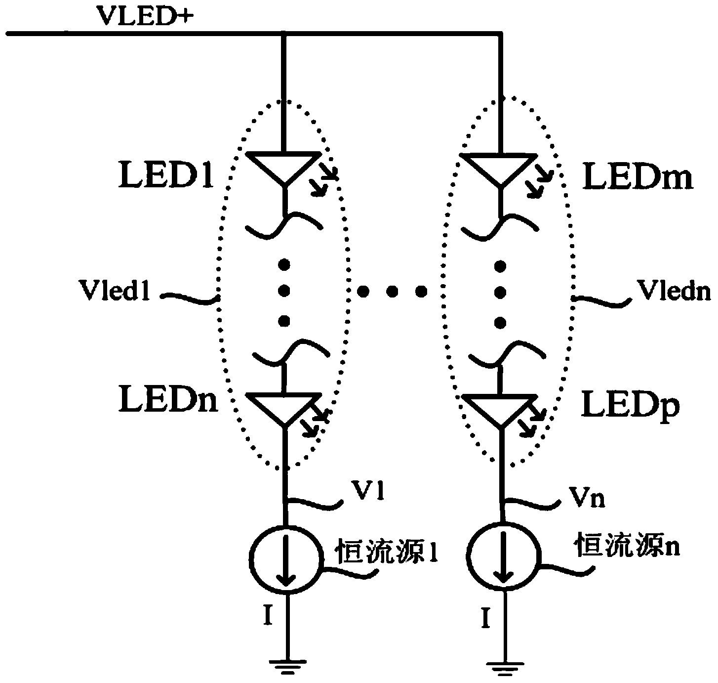
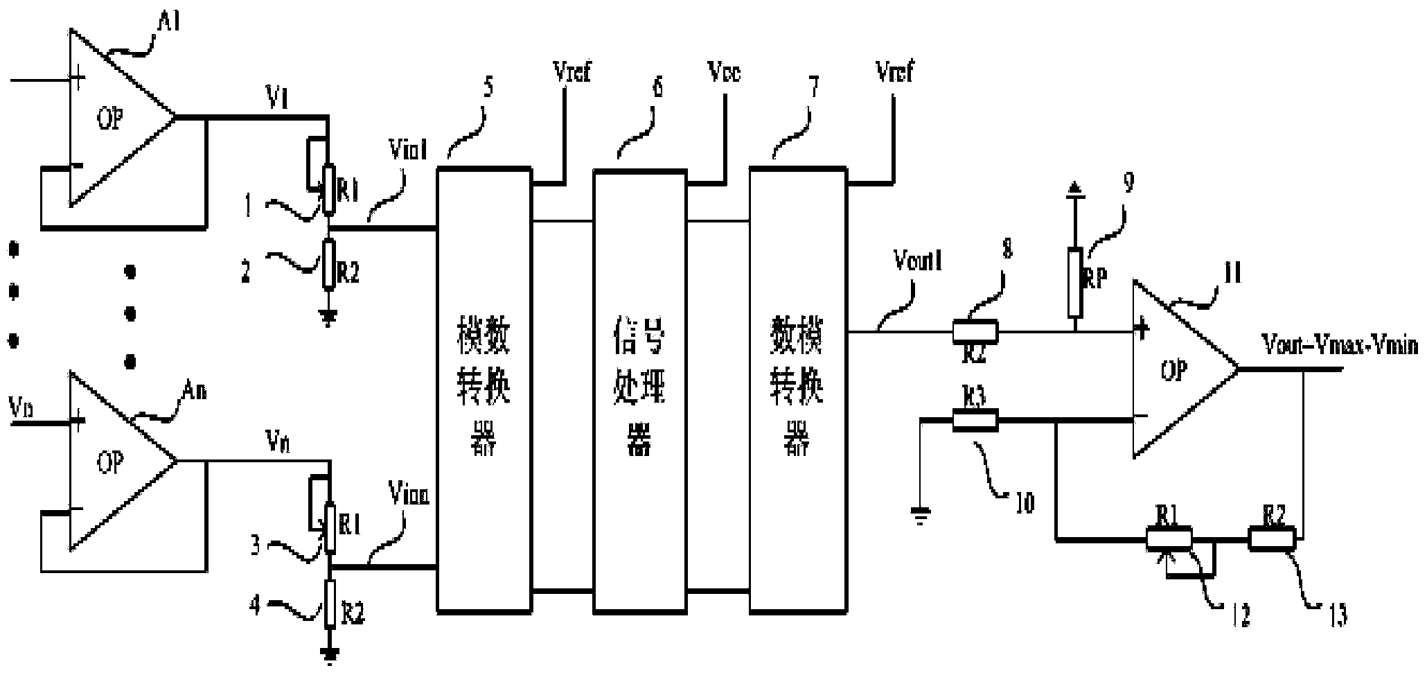
[0015] The present invention samples the voltage value on the rear constant current components of each LED light string, isolates it through a voltage follower circuit composed of an operational amplifier, and inputs it into an analog-to-digital converter to perform analog-to-digital conversion on the sampled target voltage. At this time, if the sampled voltage is too high, the sampled voltage can be processed with a certain voltage division ratio by adjusting the variable resistor, and then sent to the analog-to-digital converter for conversion. After the analog-to-digital conversion, the target voltage is input to the signal processor to perform the work of distinguishing the maximum vo...


PUM


Abstract

The invention relates to measurement devices and discloses a device for measuring the voltage difference between LED string lights. According to the device for measuring the voltage difference between the LED string lights, the voltage difference between the LED string lights when the LED string lights work can be detected rapidly, so that the production yield of a production line is increased, and the reliability of products is guaranteed. The device for measuring the voltage difference between the LED string lights comprises a voltage following circuit unit, a voltage distribution unit, an analog-digital converter, a signal processor, an analog-digital converter and a same-phase proportional operational amplifier unit, wherein the voltage following circuit unit, the voltage distribution unit, the analog-digital converter, the signal processor, the analog-digital converter and the same-phase proportional operational amplifier unit are connected in sequence, the input signal of the voltage following circuit unit serves as the negative-electrode voltage of the LED string lights, the output signal of the voltage following circuit unit enters the corresponding analog-digital converter after voltage distribution is conducted on the output signal through the voltage distribution unit, the voltage obtained through analog-digital conversion is input into the signal processor, so that maximum voltage and minimum voltage distinguishing and difference value calculating are conducted, an analog signal is obtained through conversion of the corresponding analog-digital converter, the output signal of the corresponding analog-digital converter is connected to the input end of the same-phase proportional operational amplifier unit, and the output value obtained after signal amplification is the voltage difference between the maximum value and the minimum value of a target voltage. The device is suitable for voltage testing of the LED string lights.

Description

technical field [0001] This patent relates to a measuring device for the voltage difference between LED light strings, which is suitable for testing the voltage difference between LED light strings of LED LCD TVs, monitors, lighting equipment, etc., which use multiple LEDs as light sources. It is used in various occasions such as the measurement of the voltage difference between the maximum voltage and the minimum voltage among multiple target voltages. Background technique [0002] With the development of TV and related display and lighting equipment industries, more and more LEDs are used as light sources. With its title of "green light source" and various technical advantages, LED has gradually replaced the previous light sources such as CCFL and fluorescent lamps. Most of the current LED TVs, monitors, lighting equipment, etc. use multiple LEDs as light sources to ensure their display brightness. Under normal circumstances, multiple LEDs are electrically connected by a...

Claims


Application Information

Patent Timeline
IPC IPC(8): G01R19/25
Inventor 秦博
Owner BVCH OPTRONICS SICHUAN
Why Eureka
Try Eureka