Miniaturized switch cabinet of handcart type

A handcart-type switch and handcart-type technology, applied in the field of switch cabinets, can solve problems such as complicated operation interlocking, circuit breaker shaking, and incomplete interlocking, so as to achieve safe and reliable operation, reduce the overall width, and reduce the occupied area Effect

Active Publication Date: 2015-01-07
何华斌
View PDF5 Cites 10 Cited by
  • Summary
  • Abstract
  • Description
  • Claims
  • Application Information

AI Technical Summary

Problems solved by technology

[0002] Existing switch cabinets have problems such as bulky size, complex structure, low protection level, complicated and unreliable operation interlocking, etc. Existing handcart switch cabinets generally adopt mid-mounted installation, such as KYN28 mid-mounted switch cabinet, which uses high-voltage The three-phase main circuit of the circuit breaker is arranged horizontally, and the circuit breaker can be pushed forward through the operation of the chassis car at the bottom of the circuit breaker. The horizontal layout of the main circuit of the phase leads to a large cabinet width, and the forward and backward movement of the handcart requires a certain stroke, resulting in a deep cabinet, so it occupies a large area; in addition, the upper and lower pairs of contact boxes are located in the middle of the switch cabinet, next to the At the same time, the distance between the conductive parts of the upper and lower contact boxes is small, and the insulation level is low. For example, the patent announcement number 203536842U discloses a miniaturized structure of a KYN28 central switchgear. Although the above problems have been optimized, its structure has not changed. Huge, incomplete interlocking and high cost; another example is a KYN switchgear disclosed in patent announcement No. 202454952U, which also has defects such as large volume, wide width, large floor area, complex stru

Method used


Image

  • Miniaturized switch cabinet of handcart type
  • Miniaturized switch cabinet of handcart type
  • Miniaturized switch cabinet of handcart type

Examples


Embodiment Construction

[0028] In order to make the technical means, creative features, goals and effects achieved by the present invention easy to understand, the present invention will be further described below in conjunction with specific embodiments.

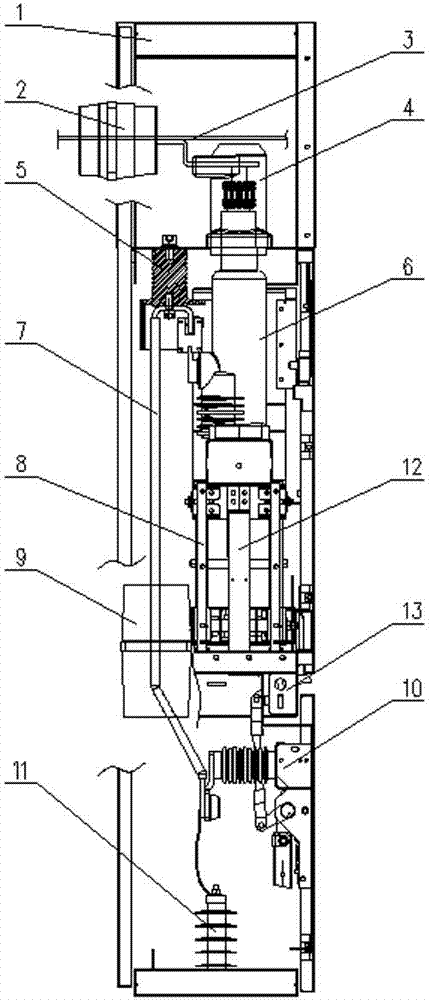
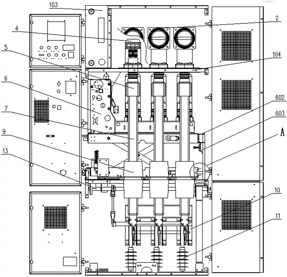
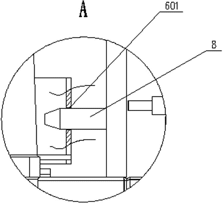
[0029] refer to Figure 1-10 , the specific embodiment adopts the following technical solutions: a miniaturized handcart switchgear, including a housing 1, a wall bushing 2, a main bus 3, an upper contact box 4, an insulating cover 5, a side-mounted handcart type Vacuum circuit breaker 6, lower bus bar 7, guide rail guide rod 8, current transformer 9, grounding switch 10, overvoltage protector 11 and grounding bar 12, housing 1 consists of left side panel 101, right side panel 102, instrument box 103, contact box mounting plate 104, circuit breaker seat plate 105, guide rail bending plate 106, left tongue plate fixing plate 107, right tongue plate fixing plate 108, upper cover plate 109, and bottom cover plate 110, circuit breaker seat plate The ...


PUM


Abstract

The invention discloses a miniaturized switch cabinet of a handcart type, and relates to a switch cabinet. The miniaturized switch cabinet is characterized in that a left tongue plate fixing plate and a right tongue plate fixing plate are respectively mounted on a left side plate and a right side plate; a wall penetrating bushing is mounted above the right side plate, and a main busbar penetrates through the wall penetrating bushing; an upper contact box and an insulating cover are respectively mounted at the upper part and the lower part of a contact box mounting plate, the upper contact box is connected with the main busbar through a copper bar, and the insulating cover is connected with the upper end of a lower end busbar through screws; a current transformer is arranged in the middle of the lower end busbar in a penetrating manner, and the lower end of the lower end busbar is fixed on an earthing switch; the current transformer is fixed at the right part of a breaker base plate, and the earthing switch is fixed on the left side plate; the lower part of a conducting loop of the earthing switch is connected with an over-voltage protector. The miniaturized switch cabinet disclosed by the invention has a high level of protection. Through the adoption of a handcart type vacuum breaker in a side mounting manner, the width is small, the cost is reduced, the requirement that power distribution equipment is miniaturized is met, and the operation is safer and more reliable through an operation interlocking function.

Description

technical field [0001] The invention relates to a switch cabinet, in particular to a miniaturized handcart type switch cabinet. Background technique [0002] Existing switch cabinets have problems such as bulky size, complex structure, low protection level, complicated and unreliable operation interlocking, etc. Existing handcart switch cabinets generally adopt mid-mounted installation, such as KYN28 mid-mounted switch cabinet, which uses high-voltage The three-phase main circuit of the circuit breaker is arranged horizontally, and the circuit breaker can be pushed forward through the operation of the chassis car at the bottom of the circuit breaker. The horizontal layout of the main circuit of the phase leads to a large cabinet width, and the forward and backward movement of the handcart requires a certain stroke, resulting in a deep cabinet, so it occupies a large area; in addition, the upper and lower pairs of contact boxes are located in the middle of the switch cabinet...

Claims


Application Information

Patent Timeline
IPC IPC(8): H02B11/133H02B1/26H02B1/14
CPCH02B11/133H02B11/167H02B11/24
Inventor 何华斌梁作鹏查道正刘兴华阮仁权张健
Owner 何华斌
Why Eureka
Try Eureka