Rotor wire end merging and cutting-off all-in-one machine

A rotor wire, all-in-one technology, used in electromechanical devices, manufacturing motor generators, electrical components, etc., can solve the problems of insufficient accuracy, unsuitable production mode, single function, etc., to increase work efficiency, save labor costs, The effect of improving production accuracy

Active Publication Date: 2015-01-07
湖州凯合电机有限公司
View PDF8 Cites 0 Cited by
  • Summary
  • Abstract
  • Description
  • Claims
  • Application Information

AI Technical Summary

Problems solved by technology

However, the function of this thread cutting machine is relatively simple, and the accuracy is not

Method used


Image

  • Rotor wire end merging and cutting-off all-in-one machine
  • Rotor wire end merging and cutting-off all-in-one machine
  • Rotor wire end merging and cutting-off all-in-one machine

Examples


Embodiment 1

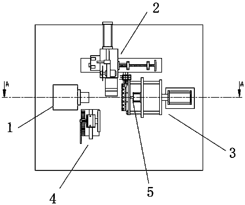
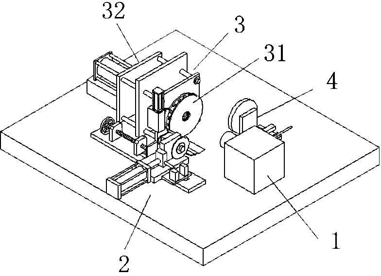
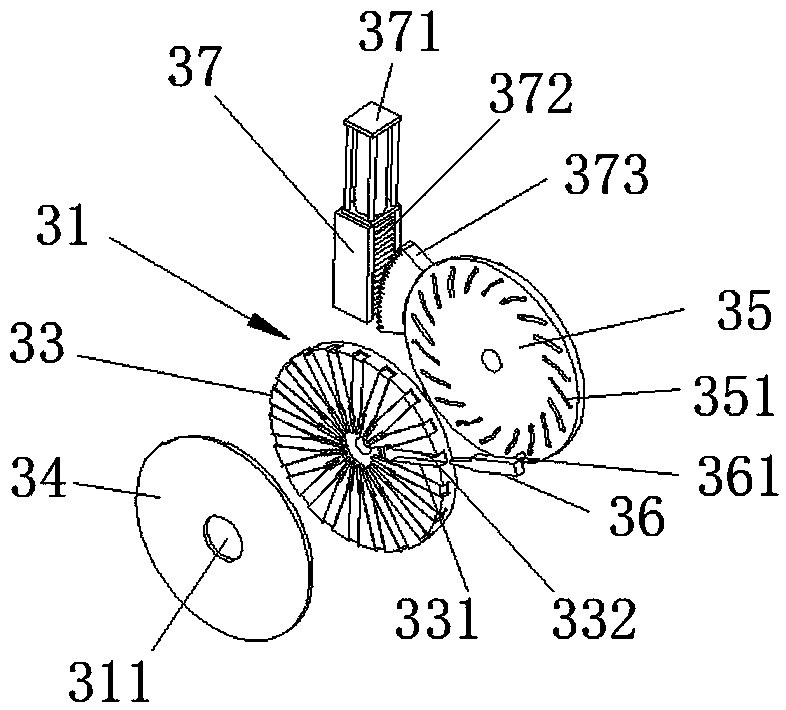
[0031] Example 1, such as Figure 1-2As shown, an integrated machine for paralleling and cutting rotor wire ends, including a rotating fixing device 1 for fixing one end of the rotor and driving the rotor to rotate, an ejecting device 5 for fixing the other end of the rotor, and a device for incorporating the coil into the exchange The inserting device 3 of the directing device slot and the cutting device 2 for cutting off the excess coil ends; the inserting device 3 includes a pin insertion device 31 and a moving device for changing the distance between the pin insertion device 31 and the rotating and fixing device 1 32. The ejecting device 5 is arranged in the moving device 32, which can greatly reduce the volume of the whole equipment and speed up the transmission efficiency. The rotating and fixing device 1 includes a motor and a rotating and fixing shaft, the rotating and fixing shaft is used for connecting one end of the rotor, and the motor is used for driving the rota...


PUM


Abstract

A rotor wire end merging and cutting-off all-in-one machine comprises a rotating and fixing device, an ejection device, an inserting device and a cutting-off device. The rotating and fixing device is used for fixing one end of a rotor and is capable of driving the rotor to rotate, the ejection device is used for fixing the other end of the rotor, the inserting device is used for merging a coil into a reverser groove, and the cutting-off device is used for cutting off residual coil ends. The inserting device comprises an insert pin device and a moving device used for changing the distance between the insert pin device and the rotating and fixing device. The rotor wire end merging and cutting-off all-in-one machine achieves integrated automatic operation of coil wire merging and cutting off, greatly improves working efficiency, reduces labor cost, improves production precision, and achieves standard and integrated flow line production.

Description

technical field [0001] The invention relates to the production equipment of the rotor, especially the production equipment of paralleling and cutting off the thread ends on the rotor. Background technique [0002] Generally, the rotor includes rotor core, armature winding (coil), shaft and commutator, such as Figure 9 shown. In the production steps, there is a process that needs to insert the coil into the slot of the commutator, and then cut off the excess coil to ensure that the coil will not exceed the commutator. In many factories, the actual operation is still manual. The coil is knocked into the slot of the commutator with a hammer and other tools, and then the excess part is cut off with scissors. This operation causes the standard length of the coil to be different, the depth of the coil to enter the slot is different, and the length of the coil after cutting is not uniform, which not only wastes manpower, but also delays work efficiency. [0003] Notification num...

Claims


Application Information

Patent Timeline
IPC IPC(8): H02K15/00
Inventor 沈钟铭袁力施国荣谢杨
Owner 湖州凯合电机有限公司
Why Eureka
Try Eureka