Battery assembly

A technology of battery components and battery cells, which is applied to battery pack parts, electrical components, secondary batteries, etc., can solve the problems of limiting the heat flow of battery cells, such as dimensional tolerances, and achieve good heat discharge, good thermal conductivity, and high insulation properties. Effect

Active Publication Date: 2015-01-07
ROBERT BOSCH GMBH
View PDF7 Cites 5 Cited by
  • Summary
  • Abstract
  • Description
  • Claims
  • Application Information

AI Technical Summary

Problems solved by technology

As a result, the transferable heat flow from the battery cells to the cooling element is limited and possibly existing dimensional tolerances between the battery cells and the cooling element are compensated.

Method used


Image

  • Battery assembly
  • Battery assembly
  • Battery assembly

Examples


Embodiment Construction

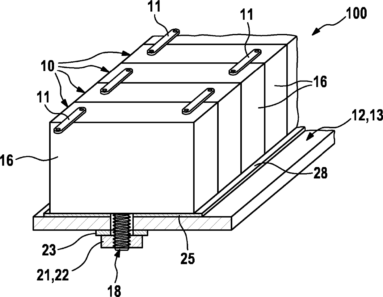
[0021] exist figure 1 shows a first battery assembly 100 according to the invention, as it is used in particular, but not limitedly, as a component of a voltage supply device for supplying energy to at least one electric drive motor in a hybrid vehicle. The battery pack 100 comprises a plurality of generally identically constructed battery cells 10 which, depending on requirements, are electrically connected in series or in parallel by means of cell connectors 11 . Obviously, it is also possible to provide a plurality of battery assemblies 100 which are in turn electrically connected to each other. In practice, an energy supply device in a hybrid vehicle may comprise, for example, approximately one hundred battery cells 10 interacting with each other.

[0022] In order to dissipate the heat losses of the individual battery cells 10 , which occur through chemical processes, in particular when electricity is drawn from the battery elements 10 , in order to thereby avoid thermal...


PUM


Abstract

The invention relates to a battery assembly (100) consisting of several battery cells (10) which are electrically connected to each other and which respectively comprise a preferably prismatic cell housing (16). Each cell housing (16) comprises at least one fastening projection (18) on the base of the cell (17), said fastening projection protruding through an opening (19) of a cooling element (12) embodied as a cooling plate (13) or as a cooling housing (35) for the cell housings (16). Said fastening projection (18) interacts with a tensioning element (22) which maintains the cell housing (16) against the cooling element (12).

Description

technical field [0001] The invention relates to a battery pack according to the preamble of claim 1 . Background technique [0002] A battery pack of this type is known from DE 10 2010 029 872 A1. The battery assembly is provided there for use in a hybrid vehicle and comprises a plurality of prismatic unit housings which are mechanically and electrically connected to one another and which each form an individual battery unit. Especially at high discharge currents or relatively high external temperatures, it is necessary to dissipate the heat lost during the discharge of the battery cells in order to avoid thermal overloading or damage to the battery cells. For this purpose, it is known from the cited documents that the unit housings are arranged with their unit bases facing a cooling plate (as far as possible) over their entire area in thermally conductive contact with the cooling plate. For this purpose, the known unit housing has projections which protrude through openin...

Claims


Application Information

Patent Timeline
Patent Type & Authority Applications(China)
IPC IPC(8): H01M2/10H01M2/02H01M6/50H01M10/647H01M10/6554H01M10/6556H01M50/103H01M50/209H01M50/227
CPCH01M10/5032H01M10/5004H01M2/0217H01M10/5057H01M2/1016H01M6/5038H01M10/5053H01M50/103H01M50/227H01M6/50H01M50/209H01M10/647H01M10/6556H01M10/6554H01M10/613Y02E60/10H01M10/653H01M10/6551
Inventor S.杜齐亚克C.科布勒R.拉姆萨耶
Owner ROBERT BOSCH GMBH
Why Eureka
Try Eureka