Eureka AIR delivers breakthrough ideas for toughest innovation challenges, trusted by R&D personnel around the world.

Valve positioner having bypass component and control valve comprised thereof

A valve positioner and component technology, applied in the direction of jet program control, valve device, valve details, etc., can solve the problems of increasing the cost and complexity of process lines and control system components, and achieve the effect of reducing downtime

Inactive Publication Date: 2015-01-14
DRESSER INC
View PDF0 Cites 1 Cited by
  • Summary
  • Abstract
  • Description
  • Claims
  • Application Information

AI Technical Summary

Problems solved by technology

While effectively offsetting potential downtime, these redundant systems still require additional hardware and software that can significantly increase component cost and complexity of process wiring and control systems

Method used


Image

  • Valve positioner having bypass component and control valve comprised thereof
  • Valve positioner having bypass component and control valve comprised thereof
  • Valve positioner having bypass component and control valve comprised thereof

Examples


Embodiment Construction

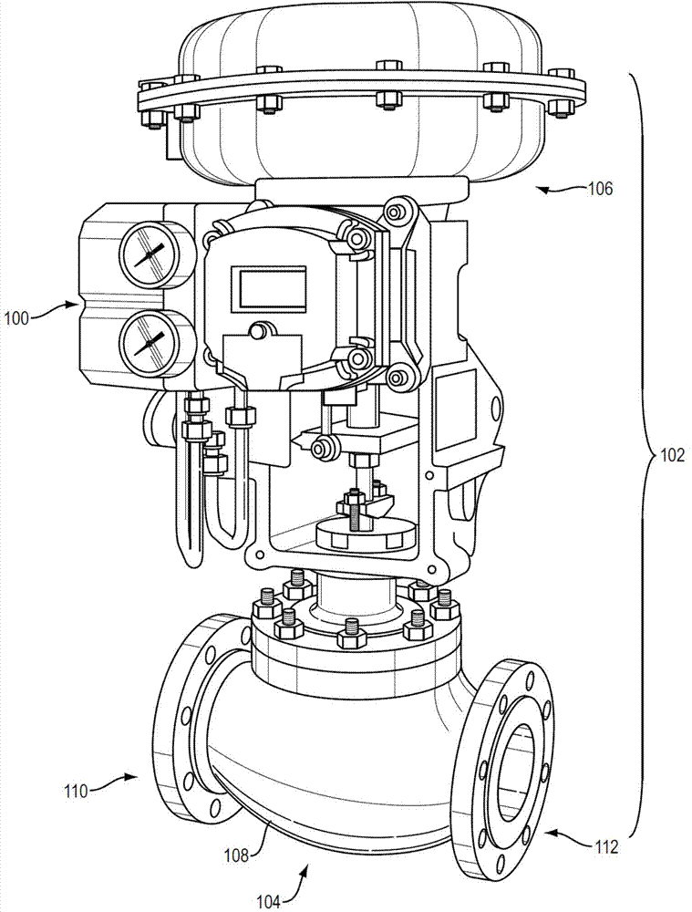
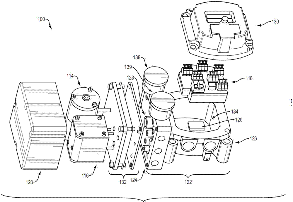
[0016] figure 1 and 2 An exemplary embodiment of a valve positioner 100 is shown having a bypass feature that continues to regulate fluid flow during in-line maintenance and repair. exist figure 1 In FIG. 1 , the valve positioner 100 is part of a control valve 102 having a fluid coupling 104 and an actuator 106 . These components of control valve 102 work in combination with valve positioner 100 to control one or more process states (eg, flow, pressure, temperature, etc.) associated with fluid flow through fluid coupling 104 . As shown, the fluid coupling 104 has a body 108 with a first inlet / outlet 110 and a second inlet / outlet 112 . The fluid coupling 104 can also have figure 1 Valves not shown in illustration. The valve is present in the body 108 . An actuator 106 is coupled to the valve to change the position of the valve (eg, from a first valve position to a second valve position). The change in position regulates fluid flow through the first inlet / outlet 110 and t...


PUM


Abstract

Embodiments of a valve positioner that can maintain operation of the control valve despite failures in one or more components. These embodiments reduce downtime by allowing in-situ repair to occur on the valve positioner. In one embodiment, the valve positioner incorporates a by-pass component, which can utilize control input signals (e.g., a 4-20 mA signal) to energize one or more components (e.g., a current-to-pressure converter) to cause the control valve to modulate fluid flow without the digital microprocessor and / or related components.

Description

technical field [0001] The subject matter disclosed herein relates to control valves, and more particularly to embodiments of valve positioners for use in control valves. Background technique [0002] Control valves regulate the transmission and distribution of fluids, such as liquids and gases. These devices are integrated in process control systems in various industries. An example of a process control system forms a control loop with remote sensors and other feedback elements to monitor process conditions (eg, temperature, pressure, etc.). In response to changes in process conditions, the control loop can generate signals that cause the control valve to alter fluid flow. [0003] Many control valves incorporate valve positioners with digital components (such as microprocessors) capable of processing these signals. These digital components enable precise control and functionality of the control valve. Certain types of digital components can also expand the positioner's...

Claims


Application Information

Patent Timeline
Patent Type & Authority Applications(China)
IPC IPC(8): F16K37/00F16K31/02
CPCF15B5/006G05B19/43F16K37/0091Y10T137/7761F15B15/202F15B21/08
Inventor S.埃斯波西托
Owner DRESSER INC
Why Eureka
Eureka Blog
Learn More