Spiral flow channel heat exchanger

A spiral flow channel and heat exchanger technology, applied in the field of heat exchange, can solve the problems of difficult processing of shell-and-tube heat exchangers, heavy opening and welding workload, poor processing quality assurance, etc., so that it is not easy to leak, Less welding workload and less resistance

Inactive Publication Date: 2015-01-14
黑龙江省金永科技开发有限公司
View PDF3 Cites 8 Cited by
  • Summary
  • Abstract
  • Description
  • Claims
  • Application Information

AI Technical Summary

Problems solved by technology

[0008] However, shell-and-tube heat exchangers are difficult to process, because the two ends of the heat transfer tube bundle are fixed on the tube sheets at both ends, the workload of opening and welding is very large, the processing quality is not guaranteed, and it is easy to occur during operation. Leakage and other faults, maintenance is also more difficult

Method used


Image

  • Spiral flow channel heat exchanger
  • Spiral flow channel heat exchanger

Examples


Embodiment Construction

[0026] The present invention will be described in further detail below in conjunction with the accompanying drawings and embodiments.

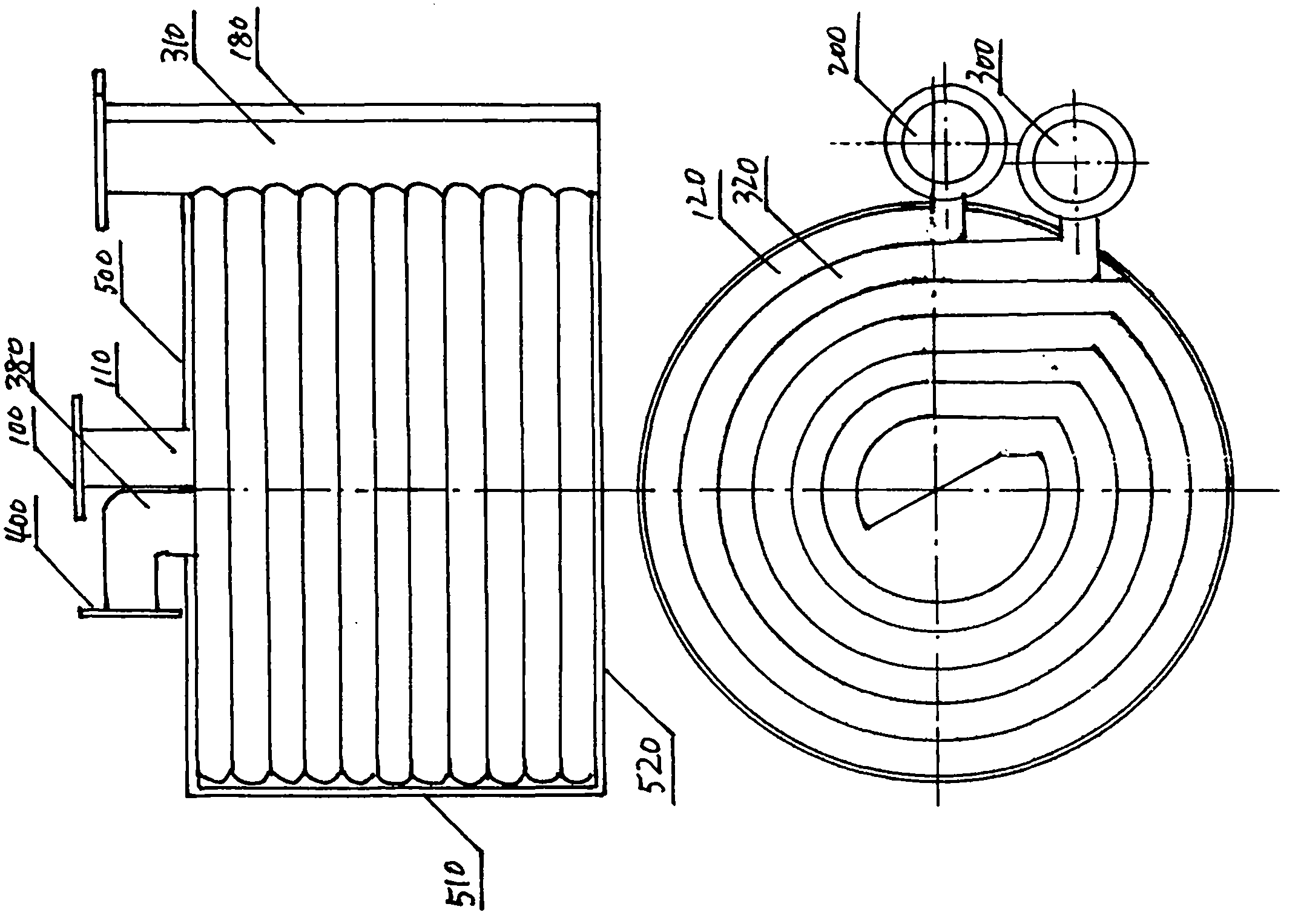
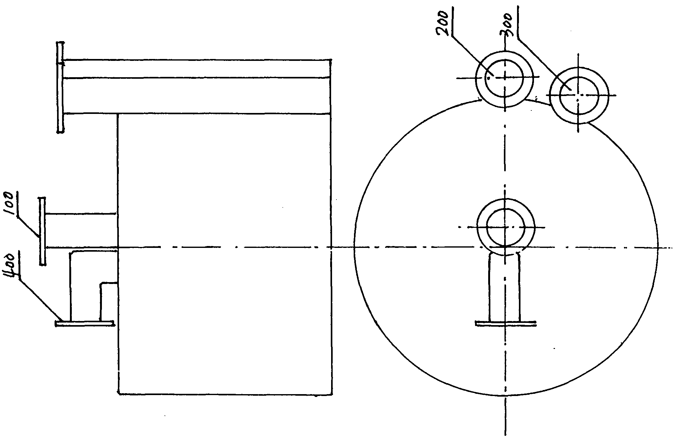
[0027] figure 1 The internal structure diagram of the embodiment of the spiral channel heat exchanger of the present invention is given.

[0028] The embodiment of the spiral channel heat exchanger of the present invention is composed of three parts: a hot water channel, a cold water channel, and a shell.

[0029] in:

[0030] The hot water flow channel is a spiral flow channel composed of a number of spiral pipe rows, including: hot water inlet 100, hot water inlet header 110, hot water spiral flow channel 120, hot water outlet header 180 and Hot water outlet 200. Hot water passes through the inlet flange of the hot water inlet 100, and enters a thick vertical pipe in the center, which is the hot water inlet header 110, and then flows horizontally into the hot water spiral flow channel 120 composed of spiral pipe rows, along the spiral Th...


PUM


Abstract

The invention provides a spiral flow channel heat exchanger. The spiral flow channel heat exchanger is in a circular table shape in appearance, and internally comprises a hot water flow channel, a cold water flow channel and a shell. The hot water flow channel comprises a hot water spiral flow channel. The cold water flow channel comprises a cold water spiral flow channel. The hot water spiral flow channel and the cold water spiral flow channel are arranged in a horizontally-spirally-spaced mode. The spiral flow channel heat exchanger is characterized in that the hot water spiral flow channel is composed of spiral pipe rows formed by connecting a plurality of horizontal spiral pipes in parallel in an up-down-stacked mode. The section of the spiral pipes is in a circular pipe or an oval pipe or a square pipe shape. The hot water passes through a hot water inlet, horizontally flows into the hot water spiral flow channel formed by the spiral pipe rows, and flows horizontally and spirally along the spiral lines from inside to outside. The flowing radius is gradually increased, and finally the hot water flows out of a hot water outlet after passing through a hot water outlet header. The cold water spiral flow channel is formed between two layers of the hot water spiral flow channel. The cold water flows horizontally and spirally along the spiral lines from outside to inside. The flowing radius is decreased gradually, and finally the cold water flows out of a cold water outlet after passing through a cold water outlet header in the center.

Description

technical field [0001] The invention relates to heat exchange technology, in particular to a spiral channel heat exchanger. Background technique [0002] A heat exchanger is a device that transfers part of the heat of a hot fluid to a cold fluid, also known as a heat exchanger. Heat exchangers are common equipment in chemical industry, petroleum, power, food and many other industrial sectors, and play an important role in production. As heat transfer equipment, heat exchangers are also widely used in the field of boiler heating and ventilation. With the rapid development of energy-saving technology, there are more and more types of heat exchangers. [0003] The shell and tube heat exchanger is composed of shell, heat transfer tube bundle, tube plate, baffle plate and tube box and other components. The shell is mostly cylindrical, and the inside is equipped with parallel tube bundles composed of heat transfer tubes, and the two ends of the tube bundles are fixed on the tub...

Claims


Application Information

Patent Timeline
Patent Type & Authority Applications(China)
IPC IPC(8): F28D9/04
CPCY02P20/10
Inventor 李金峰李伟尚德敏
Owner 黑龙江省金永科技开发有限公司
Why Eureka
Try Eureka