Shield conductor, and method of manufacturing same

A technology for shielding conductors and manufacturing methods, which is applied in cable/conductor manufacturing, conductors, and conductive connections, etc., can solve the problems of uniformizing the metal braided portion and the shielding tube, increasing the number of parts, etc., and achieves high electrical contact reliability. The effect of the number of parts

Inactive Publication Date: 2015-01-14
SUMITOMO WIRING SYST LTD
View PDF4 Cites 6 Cited by
  • Summary
  • Abstract
  • Description
  • Claims
  • Application Information

AI Technical Summary

Problems solved by technology

However, in such a connection method using fastening, it is difficult to make the contact condition between the metal braid and the outer peripheral surface of the shielding tube uniform over the enti

Method used


Image

  • Shield conductor, and method of manufacturing same
  • Shield conductor, and method of manufacturing same
  • Shield conductor, and method of manufacturing same

Examples


Embodiment 1

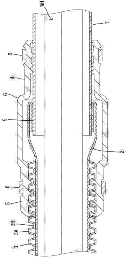
[0026] Embodiment 1 in which the shield conductor of the present invention is realized will be described with reference to the drawings. In the present embodiment, in the hybrid vehicle, the wire harness WH connecting the battery mounted in the rear compartment and the inverter mounted in the engine room is shielded and routed.

[0027] Such as figure 1 As shown, the wire harness WH is composed of a plurality of electric wires. A part of the wire harness WH is inserted into the shield tube 1 made of conductive metal. The shield pipe 1 is made of aluminum or an aluminum alloy, and is placed under the chassis of the vehicle body.

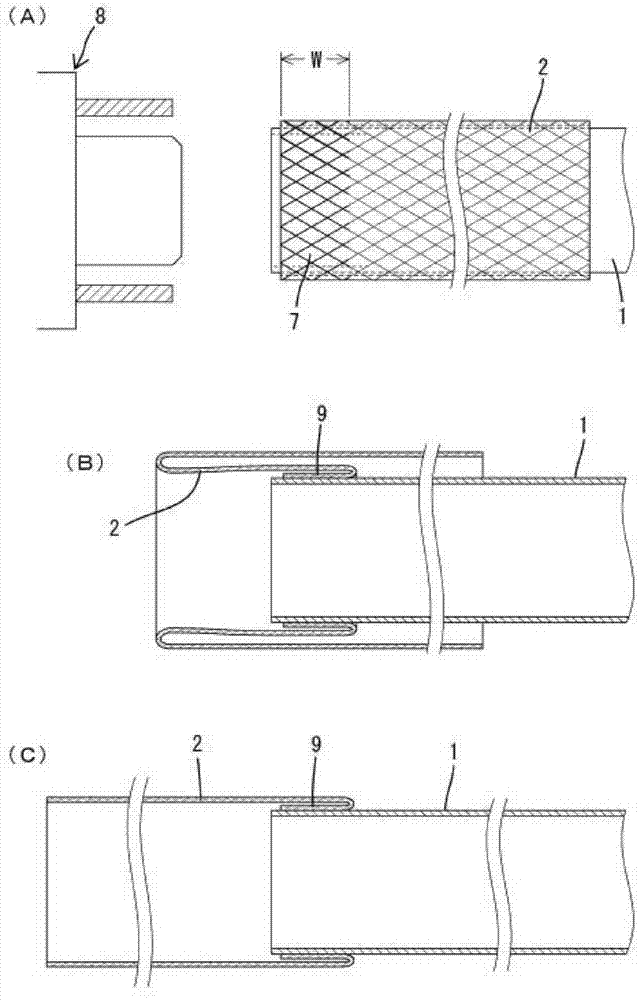
[0028] One end of the metal braid 2 is connected to one end of the shielding tube 1 . The metal braid 2 is formed, for example, by braiding copper-based metal wires with tin-plated surfaces in a mesh-like elongated cylindrical shape. The electric wire drawn out from the shielding tube 1 is inserted into this metal braided part 2 . The end of the ...

Embodiment 2

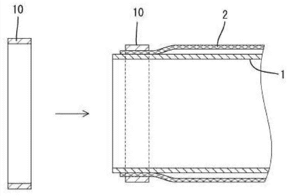
[0039] image 3 Example 2 is shown. In Embodiment 1, the metal braided part 2 and the shielding pipe 1 are directly welded, while in Embodiment 2, the metal ring 10 for welding (corresponding to the welding part for connection of the present invention) is embedded in the first embodiment before the welding operation. Up to the end of the metal braided part 2, the metal braided part 2 and the shielding tube 1 are welded by means of ultrasonic welding or the like to melt it.

[0040] The material of the metal ring 10 can be selected from materials that can be welded to the shielding tube 1 such as aluminum, aluminum alloy, copper, and copper alloy, for example. The metal ring 10 is melted by the ultrasonic welding process, and flows between the metal braid and the shielding tube through the gaps in the mesh of the metal braid. In this way, after the molten metal is solidified, the metal braided part and the shielding pipe are connected and fixed.

[0041] In addition, it is not...


PUM


Abstract

A shield conductor that shields an electrical wire includes a shield pipe and a metallic braid part that are connected together by a weld along a circumferential direction. The weld may be made by ultrasonic welding. The welding may be direct welding, or welding in which a welding member is melted and then hardened to connect the shield pipe and the metallic braid part together.

Description

technical field [0001] The present invention relates to a shielding electric conductor and its manufacturing method. Background technique [0002] Conventionally, in hybrid vehicles and electric vehicles, wiring harnesses routed between the battery and the inverter, between the inverter and the motor, etc. are often inserted through metal shielding tubes for wiring. The shielding pipe is arranged in the front-rear direction under the chassis of the vehicle body. The shielding tube has a shielding function for electric wire shielding and a function for protecting electric wires from flying stones and the like. After the shield tube is introduced into the engine room, it is connected to the inverter side through a flexible metal braid, which improves the degree of freedom in the wiring direction of the wiring harness. The metal braid is formed by weaving metal wires into a net shape, and it covers the end of the metal pipe, and generally, it is often connected by fastening w...

Claims


Application Information

Patent Timeline
IPC IPC(8): H01B7/17H01B13/22
CPCH01B13/00H01B5/12Y10T29/49117H02G3/0691H01R4/02H01R4/023H02G3/0468H02G3/0481H02G3/0666
Inventor 中井洋和大平雄贵
Owner SUMITOMO WIRING SYST LTD
Why Eureka
Try Eureka