OLED diode support with elastic connection blades

a diode support and elastic connection technology, applied in the direction of connection of coupling devices, fixed installations, lighting and heating apparatus, etc., can solve the problem of limited connection type, and achieve the effect of producing clean and simple and effective electrical connections of surface light sources

Inactive Publication Date: 2017-11-28
VALEO VISION SA
View PDF13 Cites 0 Cited by
  • Summary
  • Abstract
  • Description
  • Claims
  • Application Information

AI Technical Summary

Benefits of technology

[0011]Advantageously, the electrical tracks are produced via a metallic coating deposited on the substrate. Where appropriate, the metallic coating of the electrical tracks at the point of electrical contact is chosen so as to be compatible with the electrical contact in the place of the electrical tracks. The metallic coating in the place of the electrical contact and the electrical contact in the place of the electrical tracks can for example each include a top layer at least 1μ thick comprising a nickel-gold alloy, so as to guarantee the reliability of the electrical contact. As a variant, other alloys such as tin, silver or nickel-palladium-gold can be chosen. If so desired, the at least two electrical contact zones can be lubricated so as to increase the reliability of the electrical contact.
[0034]The provisions of the invention are advantageous in that they make it possible to produce an electrical connection of the surface light sources cleanly, simply and effectively. The blades can in fact be put in place on the added part. When assembling the support, the fitting of the added part will then ensure not only the mechanical securing of the surface light sources but also their electrical connection to the substrate.

Problems solved by technology

This type of connection is however limited to a very specific configuration in which the diodes are inserted into cavities.

Method used


Image

  • OLED diode support with elastic connection blades
  • OLED diode support with elastic connection blades
  • OLED diode support with elastic connection blades

Examples


Embodiment Construction

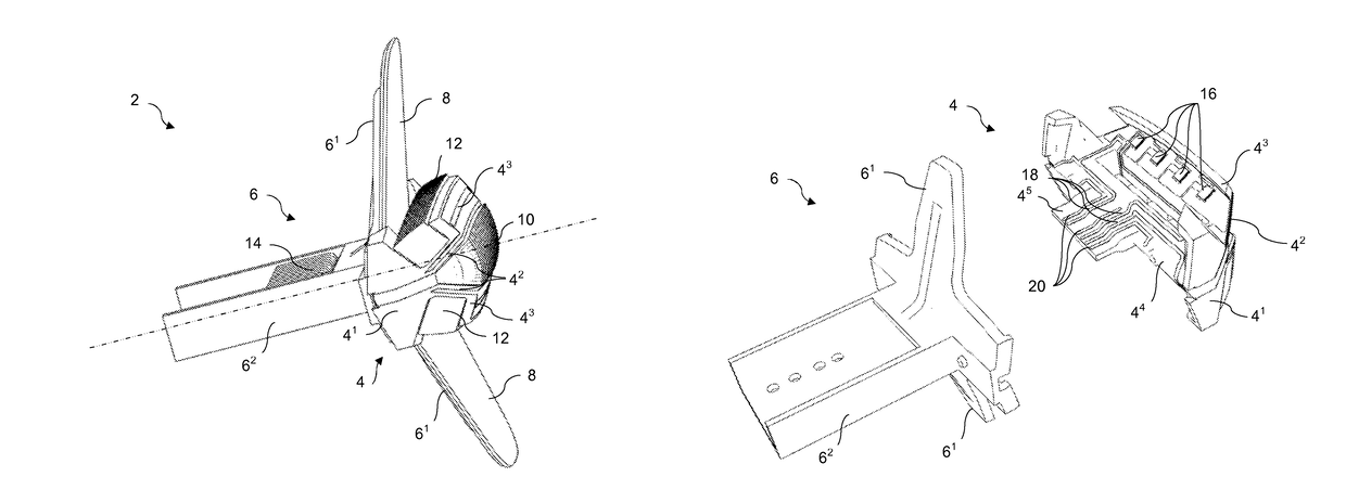
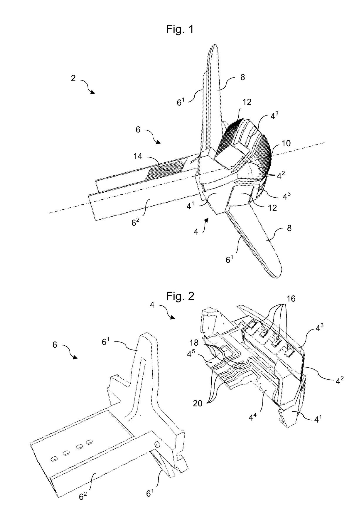
[0043]FIG. 1 illustrates a light indication module for a motor vehicle. The module 2 is configured to be housed in a casing arranged at the rear of the vehicle. It is configured to ensure a side marker light (or rear light) function, a stop light function and a direction indicator (or flashing) function.

[0044]The module 2 comprises a substrate 4 and a part 6 added onto the substrate 4. The added part 6 can be fixed to the substrate 4 by means of screws. The substrate 4 essentially comprises a central part 41, two lateral walls 42, two front walls 43 protruding from the lateral walls 42. The two lateral walls 42 form a cavity housing light sources (not visible) and a collimator 10 in order to form a light beam for a direction indicator function.

[0045]The added part 6 comprises two supports 61 and a rear part 62. The supports 61 are arranged in such a way as to protrude from the central part 41 of the substrate 4 essentially opposite one another. Each of these supports 61 supports a d...


PUM


Abstract

The invention deals with a support for light source(s) for a light module, notably for a motor vehicle, comprising a substrate; at least one surface light source of the organic light-emitting diode type supported by the substrate, the at least one surface light source comprising, at one or more edges, at least two electrical contact zones; electrical tracks deposited on the substrate; and electrical contacts between the electrical contact zones of the light source or sources and the electrical tracks. The electrical contacts comprise elastic blades, in contact under pressure with the contact zone or zones of the surface light source or sources and with the electrical tracks on the substrate.

Description

CROSS-REFERENCE TO RELATED APPLICATIONS[0001]This application claims priority to the French application 1458674 filed on Sep. 15, 2014, which application is incorporated herein by reference and made a part hereof.BACKGROUND OF THE INVENTION[0002]1. Field of the Invention[0003]The invention deals with the field of lighting and / or light indication, notably for a motor vehicle. More specifically, the invention deals with the field of lighting and of light indication by means of light-emitting diodes (LED) and organic light-emitting diodes (OLED).[0004]2. Description of the Related Art[0005]The published patent document DE 20 2013 105 597 U discloses a surface light source support of OLED diode type. The support comprises an extended substrate supporting the OLED diode and a cover extending essentially at right angles to the substrate. The OLED diode passes through the cover and comprises electrical connection zones. This document discloses, in paragraphs [0113] and [0139], that the sub...

Claims


Application Information

Patent Timeline
Patent Type & Authority Patents(United States)
IPC IPC(8): H01R12/52F21S8/10H01R12/71H01R12/00H05K3/18H05K1/02H01R13/24F21Y105/00F21Y115/15
CPCF21S48/212F21S48/217H01R12/714F21Y2105/00F21Y2115/15H05K2201/10386H01R12/52H01R13/2435H05K1/0284H05K3/185H05K2201/09118H01R9/096F21S43/195F21S43/145H01R12/00
Inventor JIN, HUIDUBOSC, CHRISTOPHEHUE, DAVIDBRIAND, MAXIMEZOJCESKI, ZDRAVKO
Owner VALEO VISION SA
Why Eureka
Try Eureka