Isolated type bridgeless electrolytic-capacitor-free low-ripple-wave constant-current power supply of LED lamp

A technology of LED lamps and electrolytic capacitors, applied in electric light sources, electric lamp circuit arrangements, light sources, etc., can solve the problems of low power factor, unsatisfactory reliability, and large volume, and achieves the improvement of electric power power, electric power efficiency, The effect of reducing THD and EMI

Inactive Publication Date: 2015-01-14
SHANGHAI ZHANKONGBI ELECTRONICS TECH +5
View PDF6 Cites 8 Cited by
  • Summary
  • Abstract
  • Description
  • Claims
  • Application Information

AI Technical Summary

Problems solved by technology

But at present, the application of DU8673 integrated chip mostly uses rectifier bridge and electrolytic capacitor, so the power factor is low, the reliability is not ideal, and the volume is large. Therefore, it is necessary to study the bridgeless, electrolytic capacitor and low ripple isolated LED lamp based on DU8673 integrated chip. Constant current power supply

Method used


Image

  • Isolated type bridgeless electrolytic-capacitor-free low-ripple-wave constant-current power supply of LED lamp

Examples


Embodiment Construction

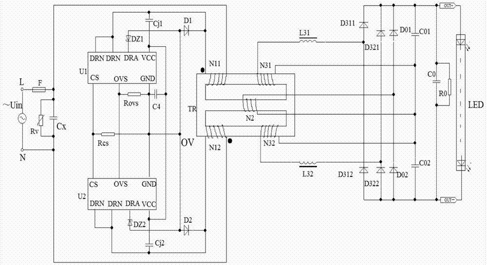
[0031] Combine below figure 1 The specific embodiment of the present invention will be further described.

[0032] No bridge, no electrolytic capacitor, low ripple isolated LED lamp constant current power supply, including: AC power supply circuit, start-up and power supply circuit, coupling output circuit and ripple suppression circuit;

[0033] The AC power supply circuit is connected to the AC power supply Uin, including a constant current drive chip U1 and a constant current drive chip U2 that are respectively controlled by the positive half-wave and negative half-wave polarity control of the AC power supply Uin to alternately work or rest half-wave, and, The AC positive half-wave current loop and the AC negative half-wave current loop are respectively controlled by the constant current driver chip U1 and the constant current driver chip U2. The currents of the above current loops all flow through the primary winding N11 and the primary The side winding N12 generates an i...


PUM


Abstract

The invention discloses an isolated type bridgeless electrolytic-capacitor-free low-ripple-wave constant-current power supply of an LED lamp. The isolated type bridgeless electrolytic-capacitor-free low-ripple-wave constant-current power supply of the LED lamp comprises an alternating-current power supply circuit, a start and power supply circuit, a coupling-out circuit and a ripple wave restraining circuit. The alternating-current power supply circuit comprises an alternating-current positive half-wave current loop and an alternating-current negative half-wave current loop. The current of the alternating-current positive half-wave current loop and the alternating-current negative half-wave current loop both flow through a primary winding N11 and a primary winding N12 of a magnetic integration transformer TR so that an induced secondary current can be generated on a center post secondary winding N2 of the magnetic integration transformer TR. The start and power supply circuit comprises a start and power supply circuit body of a constant-current drive chip U1 and a constant-current drive chip U2. The induced secondary current is rectified and filtered and then is output to the load, the LED lamp, by the coupling-out circuit. The ripple wave restraining circuit recycles harmonic waves THD and electromagnetic interference EMI, and the harmonic waves THD and the electromagnetic interference EMI are output to the load, the LED lamp, through rectification. The constant-current drive chip U1 and the constant-current drive chip U2 are DU8673 integrated chips. According to the isolated type bridgeless electrolytic-capacitor-free low-ripple-wave constant-current power supply of the LED lamp, a bridge rectifier is not adopted, so that the electric power is increased, an electrolytic capacitor is not adopted, so that the reliability is improved, the constant-current precision is high, the current ripple waves are small, the LED does not flicker, and the circuits are environmentally friendly.

Description

technical field [0001] The invention belongs to the constant-current power supply technology for LED lamps, in particular to a low-ripple isolated constant-current power supply for LED lamps without bridges and electrolytic capacitors. Background technique [0002] The DU series chip of Shanghai Duty Cycle Electronic Technology Co., Ltd. is a combination of mature low-cost analog technology and high-precision digital programming technology. Among them, DU8673 is a buck constant working in TRUQR quasi-resonant mode Current drive chip, built-in 600V high voltage MOSFET tube, mainly used in small and medium power LED constant current drive power system. DU8673 integrated chip is suitable for input power supply voltage range of 176Vac to 264Vac; output voltage of 40Vac to 80Vac, output constant current of 0.3A; power factor of 0.5. Even in the case of output short circuit, the constant current characteristic can still be maintained. But at present, the application of DU8673 in...

Claims


Application Information

Patent Timeline
Patent Type & Authority Applications(China)
IPC IPC(8): H05B37/02
Inventor 李明峰野娜常小霞石常青王希天
Owner SHANGHAI ZHANKONGBI ELECTRONICS TECH
Why Eureka
Try Eureka