Bridgeless electrolytic-capacitor-free low-ripple-wave high-power constant-current power supply of LED lamp

A technology of LED lights and electrolytic capacitors, which is applied in the direction of electric light source, electric light circuit layout, light source, etc., can solve the problems of lower reliability, loss of low-voltage power supply power, and working dead zone, so as to reduce THD and EMI and improve electric current. Power efficiency, the effect of improving electric power

Inactive Publication Date: 2015-01-14
SHANGHAI ZHANKONGBI ELECTRONICS TECH +5
View PDF6 Cites 6 Cited by
  • Summary
  • Abstract
  • Description
  • Claims
  • Application Information

AI Technical Summary

Problems solved by technology

However, due to the limited driving capability of the built-in MOSFET, DU8966 is only suitable for small and medium power LED lights below 45W, and it is difficult to drive high-power LED lights above 100W
Furthermore, the constant current power supplies for LED lamps currently using DU8966 all use bridge rectification. Bridge rectification not only loses the electric power of the low-voltage power supply, but also causes a "working dead zone" when the bridge rectifier diode itself is not conducting, reducing the Constant current power supply reliability: use electrolytic capacitors to filter at the load end to achieve low ripple of LED lights, because the life of electrolytic capacitors is much shorter than that of LED lights, reducing the service life of constant current power supplies and reducing reliability

Method used


Image

  • Bridgeless electrolytic-capacitor-free low-ripple-wave high-power constant-current power supply of LED lamp

Examples


Embodiment Construction

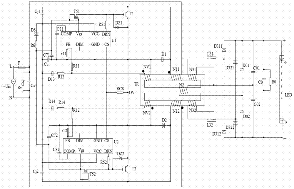
[0033] Combine below figure 1 The specific embodiment of the present invention will be further described.

[0034] Such as figure 1 As shown, there is no bridge, no electrolytic capacitor, low ripple and high power LED lamp constant current power supply, including: AC power supply circuit, control circuit, coupling output circuit and ripple suppression circuit;

[0035] The constant current power supply of the present invention adopts a magnetic integrated transformer TR, including a "day"-shaped magnetic core column, and the primary side winding N11 and the primary side winding N12 are respectively symmetrically wound on the two sides of the "day"-shaped magnetic core column On the column, the secondary winding NV1 and the secondary winding NV2 are symmetrically wound on the two side columns of the "day"-shaped magnetic core column, and the secondary winding N2 of the middle column is wound on the center of the "day"-shaped magnetic core column. On the column, the additiona...


PUM


Abstract

The invention discloses a bridgeless electrolytic-capacitor-free low-ripple-wave high-power constant-current power supply of an LED lamp. The bridgeless electrolytic-capacitor-free low-ripple-wave high-power constant-current power supply of the LED lamp comprises an alternating-current power supply circuit, a control circuit, a coupling-out circuit and a ripple wave restraining circuit. The alternating-current power supply circuit comprises a constant-current drive chip U1, a constant-current drive chip U2, an alternating-current positive half-wave current loop and an alternating-current negative half-wave current loop, wherein the constant-current drive chip U1 and the constant-current drive chip U2 are controlled by the positive half-wave and the negative half-wave of an alternating-current power supply Uin. The current of the alternating-current positive half-wave current loop and the current of the alternating-current negative half-wave current loop both flow through a primary winding N11 and a primary winding N12 of a magnetic integration transformer TR so that an induced voltage can be generated on a secondary winding NV1 and a secondary winding NV2, and then the working voltage of the constant-current drive chip U1 and the working voltage of the constant-current drive chip U2 are provided through the control circuit. An induced secondary current is generated on a center post secondary winding N2 and is output to the loaded LED lamp through the coupling-out circuit. The ripple wave restraining circuit restrains current ripple waves. According to the bridgeless electrolytic-capacitor-free low-ripple-wave high-power constant-current power supply of the LED lamp, a bridge rectifier and an electrolytic capacitor are not adopted, so that the electric power is increased, the reliability is improved, the drive capability of the chips is improved through expanded current, the working temperature of the chips is lowered, the service life of the chips is prolonged, the constant-current precision is high, the current ripple waves are small, the LED lamp does not flicker, and the circuits meet the environmental-friendliness principle.

Description

technical field [0001] The invention belongs to the LED lamp constant-current power supply technology, in particular to a bridgeless, electrolytic capacitor, low ripple and high-power constant-current power supply for LED lamps. Background technique [0002] The DU series chips of Shanghai Duty Cycle Electronic Technology Co., Ltd. combine mature low-cost analog technology and high-precision digital programming technology. Among them, the DU8966 chip is one of the LED constant current power driver chips with excellent cost performance. Each pulse closed-loop constant current control technology is suitable for wide power supply voltage, wide load voltage and wide inductance parameters. The constant current accuracy is 3%, high PF power factor, low harmonic THD; DU8966 built-in quasi-resonant TRUQR technology, Each pulse of the power electronic switch can realize real "valley switching", which reduces the EMI disturbance level, power electronic switch loss and temperature rise...

Claims


Application Information

Patent Timeline
Patent Type & Authority Applications(China)
IPC IPC(8): H05B37/02
Inventor 李明峰野娜常小霞石常青王希天
Owner SHANGHAI ZHANKONGBI ELECTRONICS TECH
Why Eureka
Try Eureka