Settling tank for sewage treatment

A technology of sewage treatment and sedimentation tank, which is applied in the direction of flocculation/sedimentation water/sewage treatment, settling tank, feeding/discharging device of settling tank, etc. problems such as mud, to achieve the effect of reducing concentration, ensuring treatment effect and improving sedimentation effect

Inactive Publication Date: 2015-01-21
YUNNAN HEXUN ENVIRONMENTAL TECH CO LTD
View PDF5 Cites 4 Cited by
  • Summary
  • Abstract
  • Description
  • Claims
  • Application Information

AI Technical Summary

Problems solved by technology

[0005] The present invention aims at the problems of serious sludge floating and suspended solids in the effluent caused by the inability to discharge the sludge in time in the existing sedimentation tank, and provides a sedimentation tank with good sedimentation effect by improving the structure of the sedimentation tank, which can significantly reduce the phenomenon of sludge floating and sedimentation tanks with effluent suspended solids content

Method used


Image

  • Settling tank for sewage treatment
  • Settling tank for sewage treatment
  • Settling tank for sewage treatment

Examples


Embodiment 1

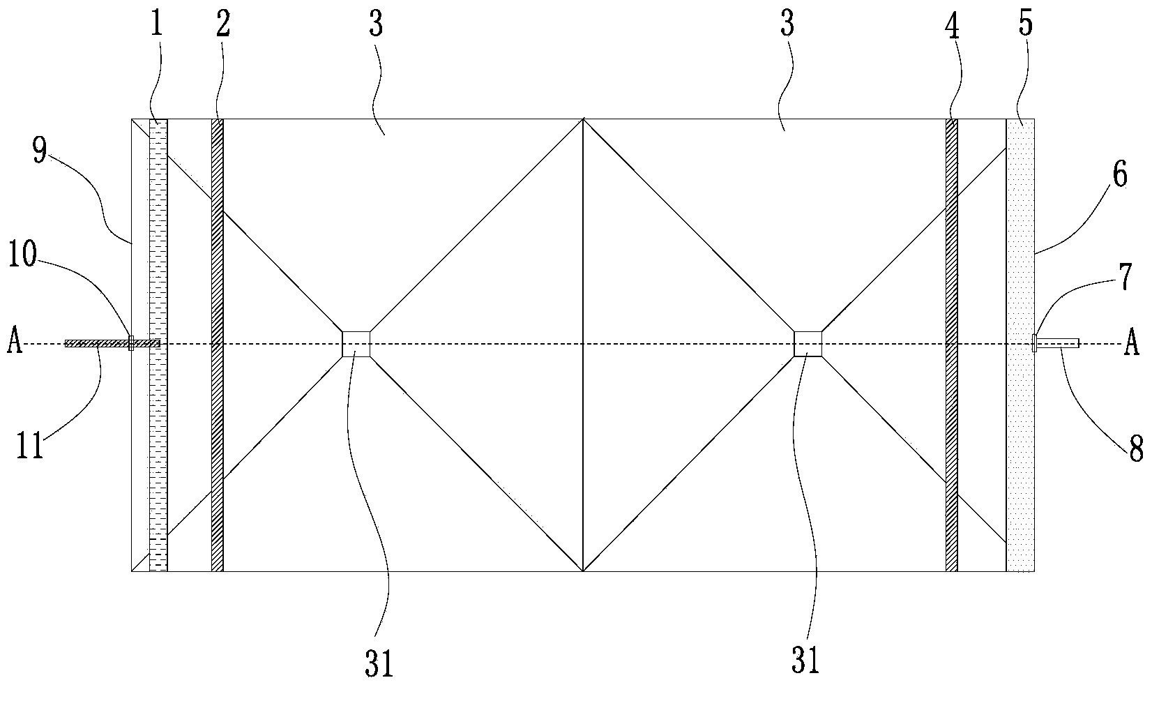
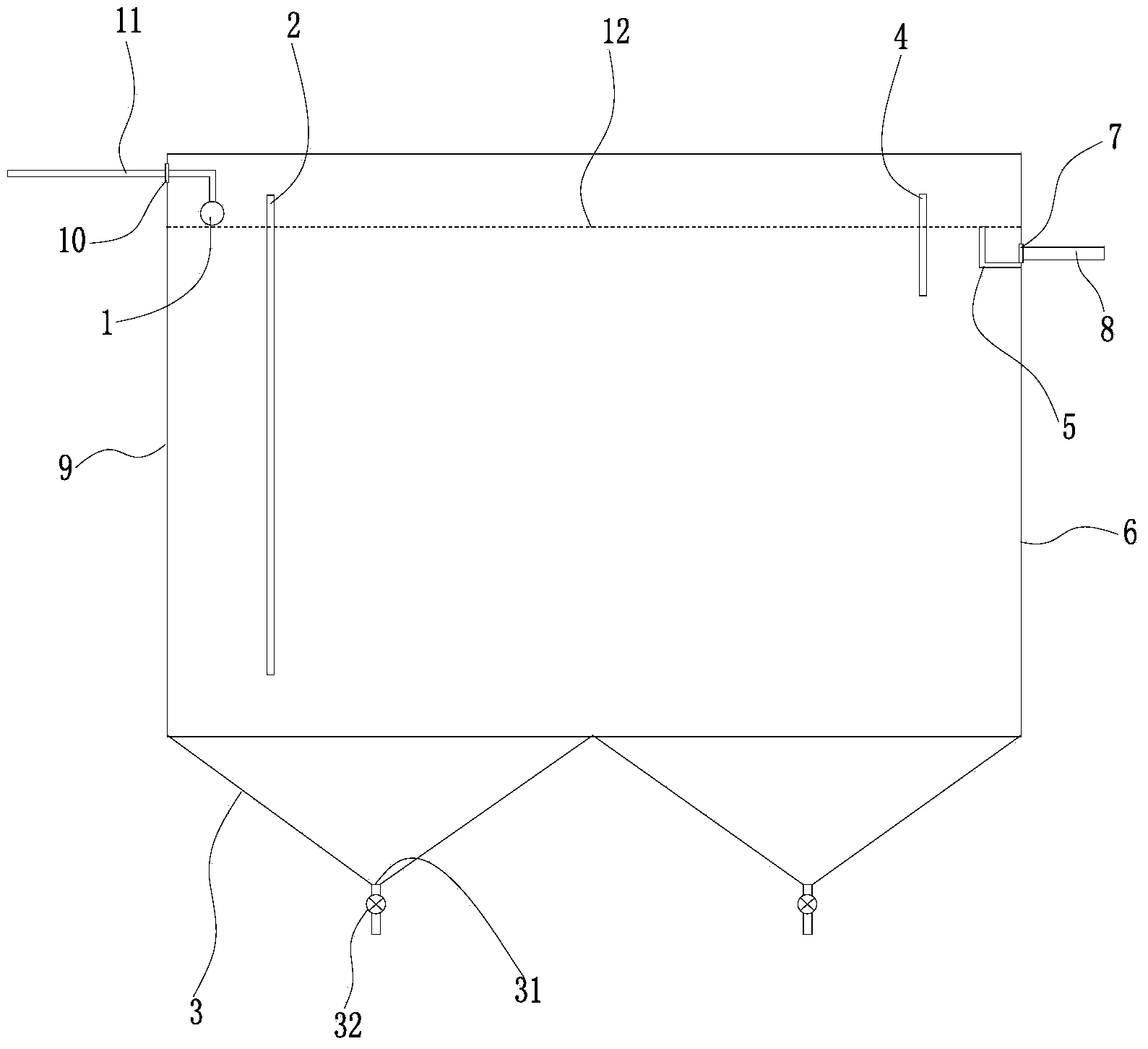
[0021] refer to Figure 1-2 A settling tank for sewage treatment provided in this embodiment includes a tank body and a conical sludge bucket 3, and a water inlet 10, a water outlet 7, a first baffle plate 2, Second baffle plate 4, water inlet area, sedimentation area, water outlet area, water distribution pipe 1, water inlet pipe 11 and water outlet weir 5.

[0022] The pool body is a cube with a height of 2m. Two conical sludge hoppers 3 are arranged side by side at the bottom of the pool body, and the upper edge of the conical sludge hopper 3 is fixedly connected with the bottom of the pool body, so that the pool body and the two conical sludge hoppers 3 constitute a storage tank. Storage space for sewage and sludge. A row of mud outlets 31 are respectively arranged at the bottom of the conical sludge hopper 3, and a mud discharge valve 32 is installed at the mud discharge outlet 31. The sludge is discharged in time or flows into other institutions, such as the sludge re...

Embodiment 2

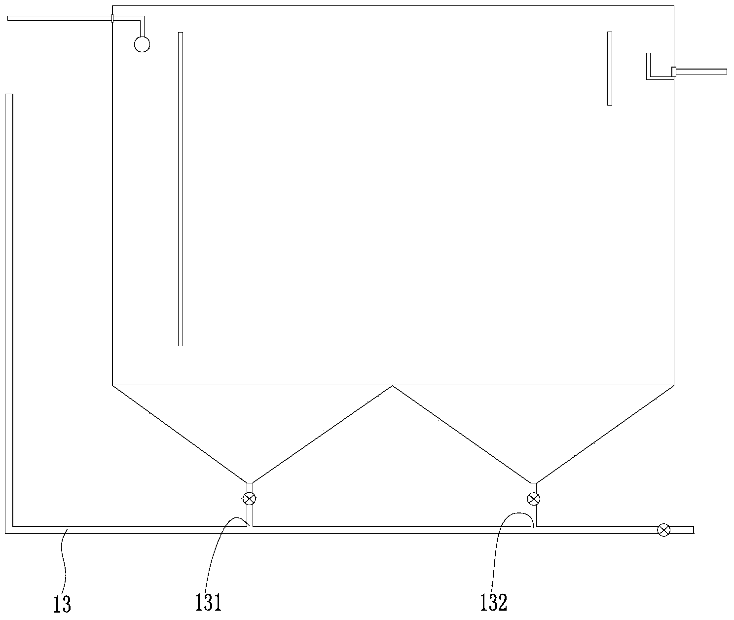
[0027] like image 3As shown, the sedimentation tank for sewage treatment provided in this embodiment has basically the same structure as that in Embodiment 1, except that a sludge return mechanism 13 is provided at the bottom of the tank. The sludge return mechanism 13 includes a first sludge inlet 131 and a second sludge inlet 132, and the first sludge inlet 131 and the second sludge inlet 132 are respectively connected to two conical sludge hoppers through pipes. The two sludge inlets are finally joined together through pipelines to form a main pipeline to transport sludge to other treatment tanks (such as pre-denitration tanks). The sludge return mechanism 13 used in this embodiment is an air-lift sludge return mechanism, and in other embodiments, other forms of sludge return mechanisms can also be used.

[0028] In other embodiments, the distance between the bottom of the second baffle and the highest liquid level of the pool body can also be set to be 15-30 cm, and the ...


PUM


Abstract

The invention relates to the technical field of sewage treatment, in particular to a settling tank for sewage treatment. A first baffle plate and a second baffle plate are arranged inside the settling tank to divide the settling tank into a water inlet zone, a settling zone and a water outlet zone; sewage enters the settling tank from a water inlet, moves in the water inlet zone from top to bottom, flows into the settling zone from the lower part of the first baffle plate, flows into the water outlet zone from the lower part of the second baffle plate, and moves upwards inside the settling zone by inclining towards the bottom of the second baffle plate; most of particles in the sewage settle due to gravity, the sewage flows into the water outlet zone and moves upwards, and residual particles in the sewage further settle, so that the settling effect of the settling tank is improved and the concentration of suspended substances in effluent water of the settling tank is reduced; the top of the second baffle plate is set to be higher than the highest liquid level of the settling tank, so that possible floating sludge on the liquid surface can be prevented from flowing into the water outlet zone, and accordingly, the treatment effect of the settling tank is ensured.

Description

technical field [0001] The invention relates to the technical field of sewage treatment, in particular to a sedimentation tank for sewage treatment. Background technique [0002] With the development of my country's economy and society, the crisis of water resources and the pollution of the water environment are intensifying, and the discharge of various sewage / wastewater has increased significantly, which seriously threatens the water environment and has become one of the hot spots in the field of environmental protection at home and abroad. Since the "Twelfth Five-Year Plan", the state has intensively issued a number of environmental protection and governance related policies, and its focus has gradually shifted from industrial and urban pollution control to comprehensive environmental management in villages and towns. Village and town sewage treatment has become an environmental protection problem that needs to be solved urgently. [0003] At present, the treatment of var...

Claims


Application Information

Patent Timeline
Patent Type & Authority Applications(China)
IPC IPC(8): B01D21/02B01D21/24C02F1/52
Inventor 裴廷权梅峰何海波李文生周洪昌张松涛舒敏玉汪欢杜兰
Owner YUNNAN HEXUN ENVIRONMENTAL TECH CO LTD
Why Eureka
Try Eureka