
Welding positioning device

A welding positioning and positioning plate technology, applied in the field of mechanical processing, can solve problems such as deformation, and achieve the effects of convenient use, convenient compression and loosening, and good practicability

Inactive Publication Date: 2015-01-21
CHONGQING WINSTAR PRECISE MACHINERY
View PDF8 Cites 3 Cited by
  • Summary
  • Abstract
  • Description
  • Claims
  • Application Information

AI Technical Summary

Problems solved by technology

[0003] The technical problem to be solved by the present invention is to provide a welding positioning device to prevent obvious deformation of the thin-walled ring gear after welding

Method used


Image

  • Welding positioning device
  • Welding positioning device

Examples


Embodiment Construction

[0012] Below in conjunction with accompanying drawing and embodiment the present invention will be further described:

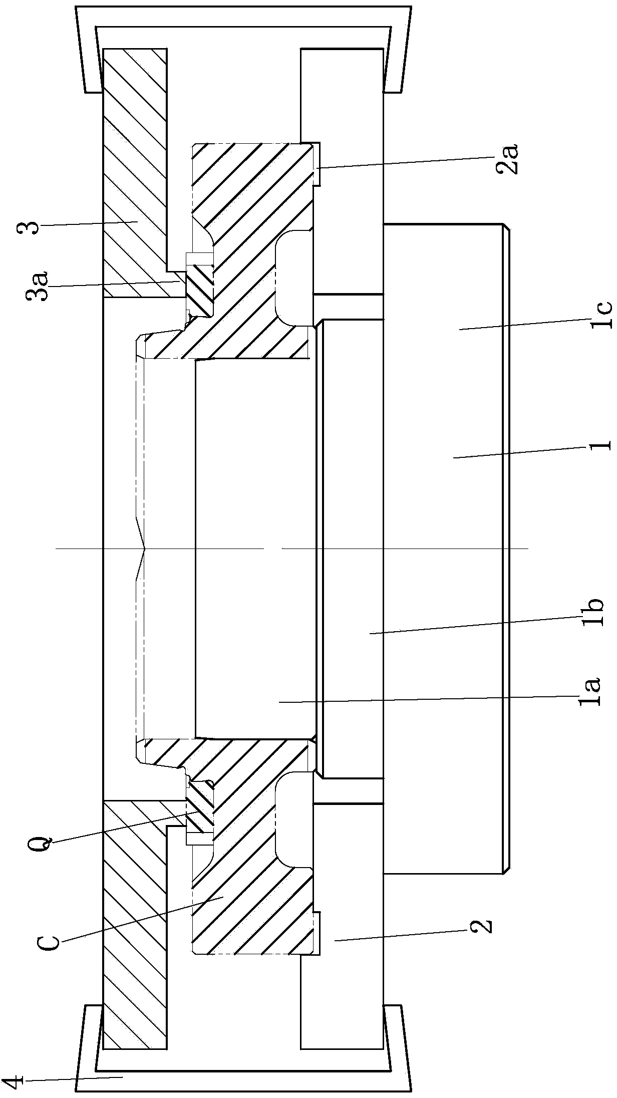
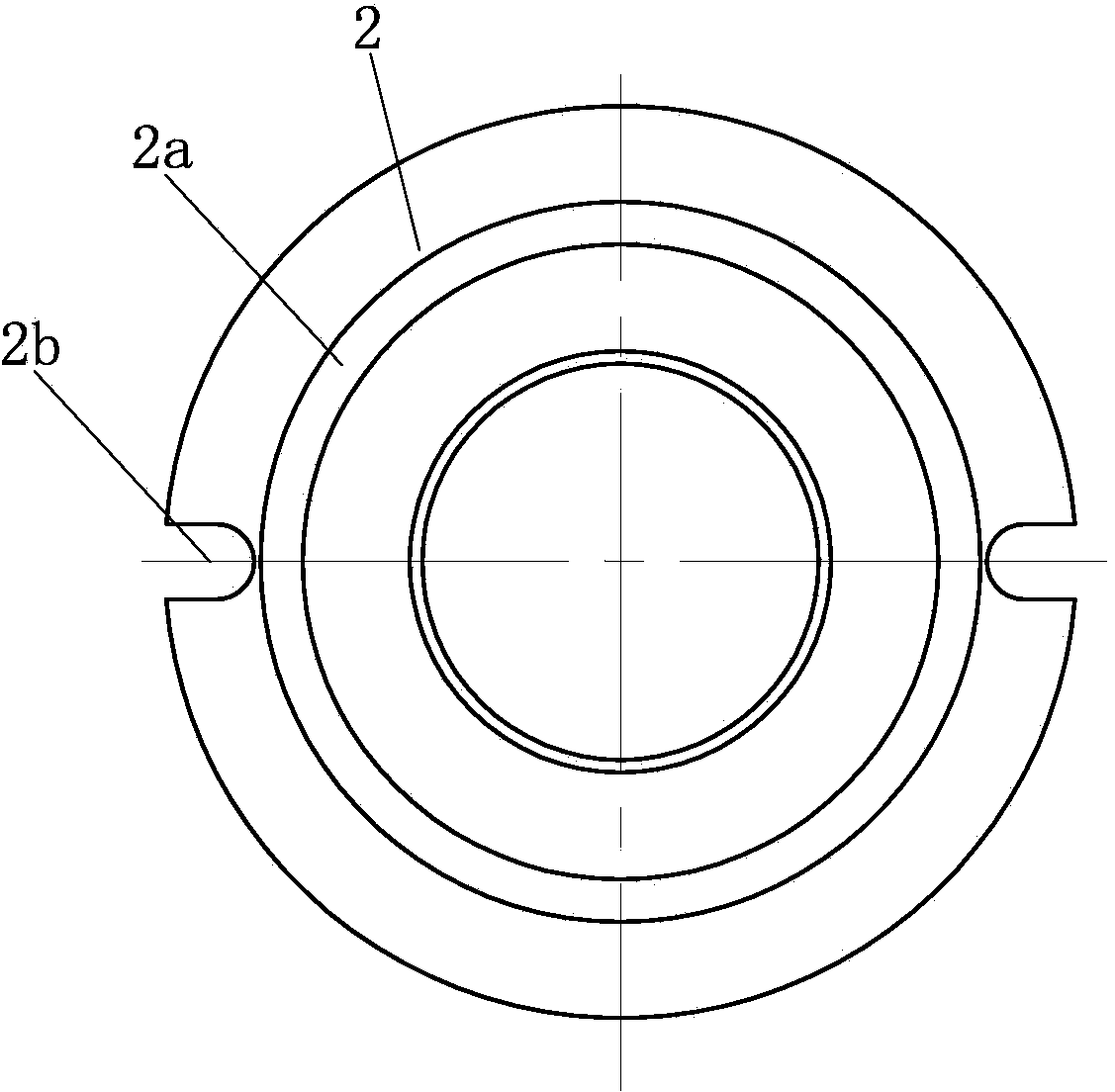
[0013] Such as figure 1 , 2 As shown, a welding positioning device is mainly composed of a welding support base 1, a lower positioning plate 2, an upper positioning plate 3 and a pressing block 4. Wherein, the welded support base 1 is a three-stage stepped shaft structure, which includes a small-diameter section 1a, a middle-diameter section 1b, and a large-diameter section 1c from top to bottom. The lower positioning plate 2 is set on the welding support seat 1, the lower plate surface of the lower positioning plate 2 is attached to the upper end surface of the large diameter section 1c, and the upper plate surface of the lower positioning plate 2 is provided with a central positioning groove 2a . Two n-shaped slots 2b are evenly distributed along the circumference of the lower positioning plate 2 , and the n-shaped slots are opened on the edge of the low...


PUM


Abstract

The invention discloses a welding positioning device. A welding support base is of a three-section type step shaft structure and sequentially comprises a small-diameter section, a medium-diameter section and a large-diameter section from top to bottom. A lower positioning plate is arranged on the welding support base in a sleeving mode, the lower plate surface of the lower positioning plate is attached to the upper end face of the large-diameter section, and the upper plate surface of the lower positioning plate is provided with a center positioning groove; an upper positioning plate is arranged over the lower positioning plate, the upper positioning plate is provided with a center hole, and the lower plate surface of the upper positioning plate is provided with a center positioning boss. During welding, a gear is arranged on the small-diameter section of the welding support base in a sleeving mode, a protrusion on the edge of the bottom face of the gear is clamped into the center positioning groove in the lower positioning plate, and finally the lower positioning plate and the upper positioning plate are tightly pressed through at least two pressing blocks. The gear is well positioned through the lower positioning plate, the gear and a gear ring are tightly clamped by means of the upper positioning plate and the lower positioning plate, pressing force is large, and accordingly the gear ring is effectively prevented from deforming obviously when heated during welding, and welding quality is guaranteed.

Description

technical field [0001] The invention belongs to the field of mechanical processing and relates to a welding positioning device. Background technique [0002] In the field of gear and thin-walled ring gear assembly, since the ring gear is a thin-walled part, the ring gear is prone to obvious deformation after welding, resulting in unqualified quality. Therefore, it is urgent to solve the above technical problems. Contents of the invention [0003] The technical problem to be solved by the present invention is to provide a welding positioning device to prevent obvious deformation of the thin-walled ring gear after welding. [0004] The technical scheme of the present invention is as follows: a welding positioning device, characterized in that it includes a welding support seat (1), a lower positioning plate (2) and a pressing block (4), wherein the welding support seat (1) is a three-stage Stepped shaft structure, from top to bottom are small diameter section (1a), middle d...

Claims


Application Information

Patent Timeline
Patent Type & Authority Applications(China)
IPC IPC(8): B23K26/70B23K37/04
CPCB23K37/0443
Inventor 段含辉
Owner CHONGQING WINSTAR PRECISE MACHINERY
Learn More