

Flange type sleeve welding station
A sleeve welding and flange-type technology, applied in welding equipment, auxiliary welding equipment, welding/cutting auxiliary equipment, etc., can solve the problems of low welding precision, high labor intensity, low welding efficiency, etc., and achieve reasonable layout and structure Compactness, the effect of improving productivity and welding accuracy
- Summary
- Abstract
- Description
- Claims
- Application Information
AI Technical Summary
Problems solved by technology
Method used
Image

Examples
Embodiment Construction
[0034] Below in conjunction with accompanying drawing and embodiment the present invention will be further described:
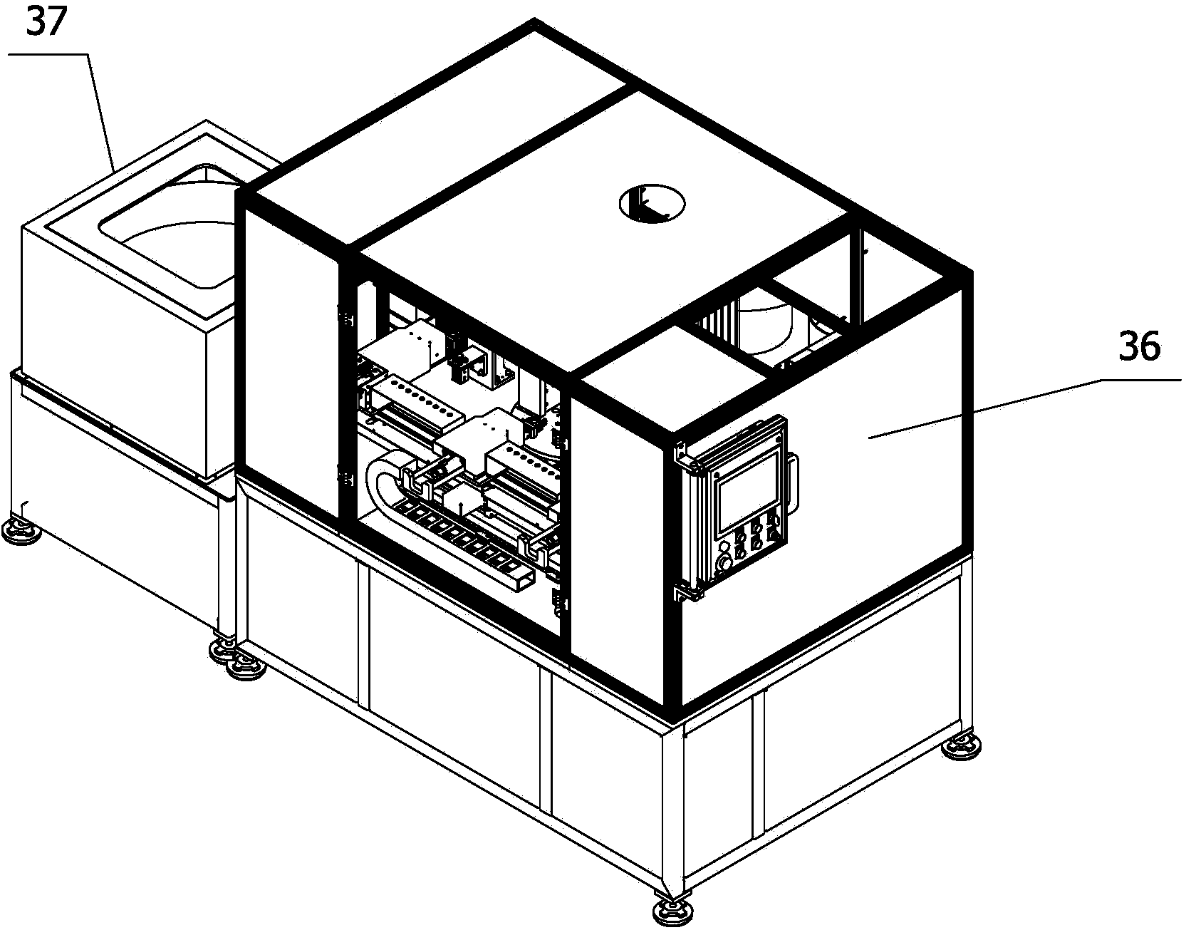
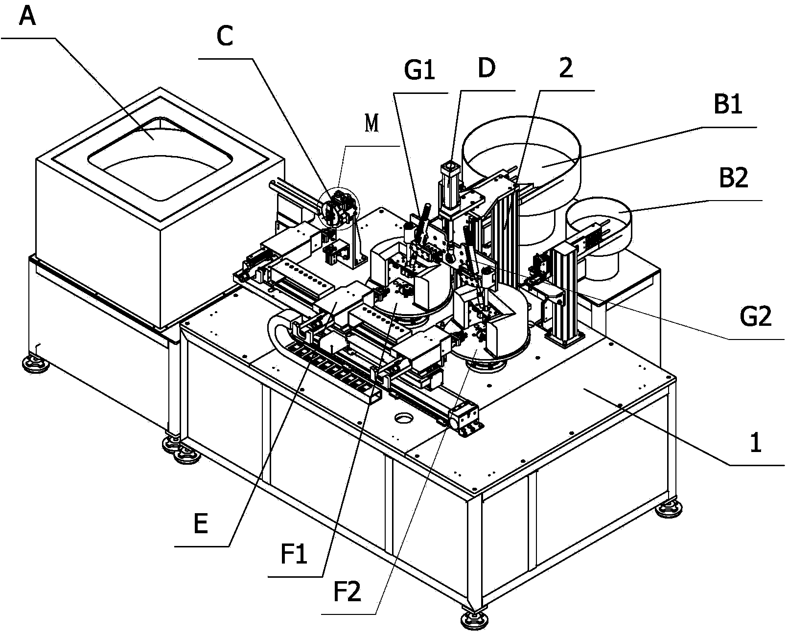
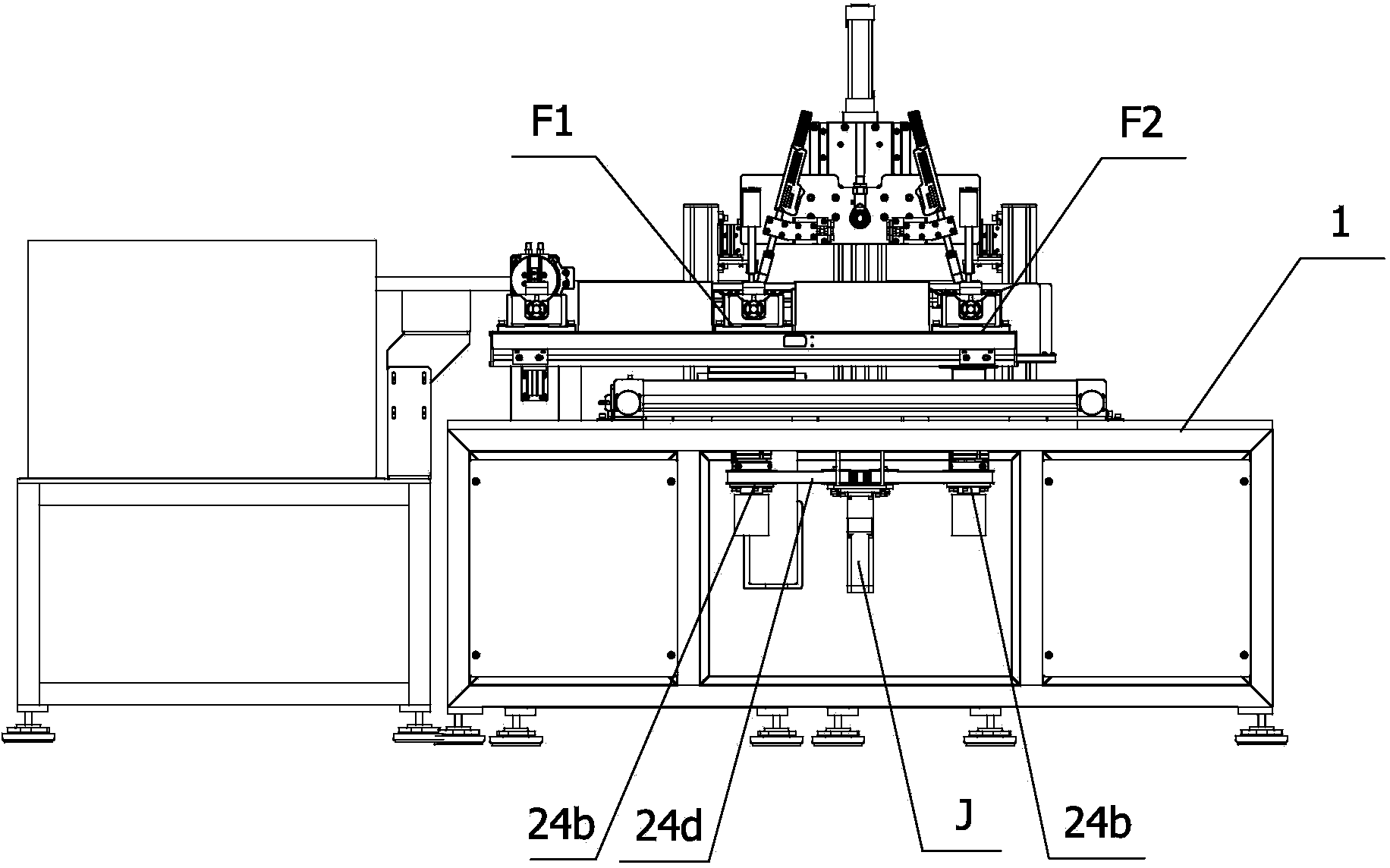
[0035] to combine figure 1 —— Figure 5 As shown, a flange-type sleeve welding station is mainly composed of a workbench 1, a pipe fitting vibrating feeder A installed on the workbench 1, a first flange vibrating feeder B1, and a second flange vibrating feeder. The feeder B2, the flip feeding mechanism C, the welding torch support assembly D, the workpiece clamping manipulator mechanism E, the first workpiece welding rotation assembly F1 and the second workpiece welding rotation assembly F2 are composed of several parts.
[0036] The pipe vibrating feeding machine A, the turning feeding mechanism C, and the welding torch support assembly D are arranged on the workbench 1 from left to right in sequence. The welding torch support assembly D is mainly composed of the welding torch head column 2 and two left and right symmetrically arranged first and second wel...
PUM
 Abstract
Description
Claims
Application Information