
Motor sweeper cab

A technology for cabs and cleaning vehicles, which is applied in the field of vehicle cabs, and can solve problems such as the influence of the driver's line of sight and field of vision, narrow lighting area, and inability to guarantee the adhesion surface and adhesion force, so as to increase safety and easy identification, increase The effect of contact area and increasing the lighting range

Inactive Publication Date: 2015-01-21
扬州市和力机械钣金有限公司
View PDF0 Cites 0 Cited by
  • Summary
  • Abstract
  • Description
  • Claims
  • Application Information

AI Technical Summary

Problems solved by technology

[0002] At present, most of the cabs of cleaning machines are very ordinary, and the sealing performance, noise reduction performance, and thermal insulation performance of the cab are average. When working in some dusty environments, the environment in the cab is very poor, which affects the health of the driver. At the same time, the lighting area is generally relatively narrow, which affects the cleaning work; moreover, the windshield is mostly glued with adhesive during the installation process. If the installation pressure is too large, the adhesive will overflow to the surrounding area, affecting the appearance and the vision of the windshield. If the installation pressure is too small, the adhesive surface and adhesive force cannot be guaranteed, and it will easily fall off after a long time. Moreover, when the external light directly enters the cab through the glass of the cab, the driver's line of sight and field of view are likely to be greatly affected, which is very uncomfortable. convenient

Method used


Image

  • Motor sweeper cab

Examples


Embodiment Construction

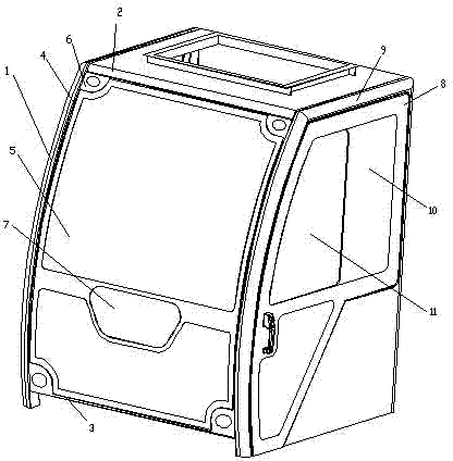
[0013] A kind of sweeper cab, it comprises front windshield panel 1, car door panel and top plate, described front windshield panel 1 comprises front frame, curved windshield glass 5 and illuminator installation panel 7, and described front frame is made of The top strip 2, the bottom strip 3 and two arc-shaped side strips 4 are formed. The top strip 2, the bottom strip 3 and the side strips 4 are provided with interconnected grooves for the four sides of the arc-shaped windshield 5 to be inserted. The windshield 5 is connected and fixed with the front frame through the groove, and the four corners of the front and back of the front frame are respectively provided with fan-shaped pressing plates 6, and the four corners of the described pressing plate 6 are connected and fixed with the windshield 5; The car door panel includes a side frame and a car door 8, and the upper side and the side of the car door 8 are respectively provided with a protective plate 9 connected to the side...


PUM


Abstract

The invention relates to a motor sweeper cab. The motor sweeper cab comprises a front screen panel, a sweeper door panel and a top plate. The front screen panel comprises a front frame, an arc windscreen and a lighting lamp installing panel. The front frame is composed of a top strip, a bottom strip and two arc side strips. The top strip, the bottom strip and the side strips are provided with grooves communicated with one another, and the four edges of the arc windscreen can be inserted into the grooves. The windscreen is fixedly connected with the front frame through the grooves. Fan-shaped pressing plates are arranged at the four corners of the front face of the front frame and the four corners of the back face of the front frame respectively. The pressing plates are fixedly connected with the four corners of the windscreen. The sweeper door panel comprises a side frame and a sweeper door. Protection plates connected to the side frame are arranged at the upper portion and the side portions of the sweeper door. The lower edges of the protection plates are connected with sealing strips. The motor sweeper cab is simple in structure, attractive in appearance, safe, large in lighting range and good in sealing performance, leakage of a bonding agent is prevented, recognition is easy, glass connecting is firm, and sunshine dazzling is prevented.

Description

technical field [0001] The invention relates to a cab of a vehicle, in particular to a cab of a cleaning vehicle. Background technique [0002] At present, most of the cabs of cleaning machines are very ordinary, and the sealing performance, noise reduction performance, and thermal insulation performance of the cab are average. When working in some dusty environments, the environment in the cab is very poor, which affects the health of the driver. At the same time, the lighting area is generally relatively narrow, which affects the cleaning work; moreover, the windshield is mostly glued with adhesive during the installation process. If the installation pressure is too large, the adhesive will overflow to the surrounding area, affecting the appearance and the vision of the windshield. If the installation pressure is too small, the adhesive surface and adhesive force cannot be guaranteed, and it will easily fall off after a long time. Moreover, when the external light directly...

Claims


Application Information

Patent Timeline
Patent Type & Authority Applications(China)
IPC IPC(8): B62D33/06B60J10/02B60J1/20B60J10/72B60J10/76
CPCB62D33/06B60J3/00
Inventor 柏斗国
Owner 扬州市和力机械钣金有限公司
Learn More