Breathing automatic dehydration oil return system and method for siphon oil tank

An oil return system, siphon type technology, applied in the field of breathing automatic dehydration oil return system, can solve the problems of low dehydration efficiency and low dehydration quality, and achieve the effect of good oil quality, high dehydration efficiency and high degree of automation

Active Publication Date: 2017-06-27
GUANGZHOU DAY WO AUTOMATION IND
View PDF8 Cites 0 Cited by
  • Summary
  • Abstract
  • Description
  • Claims
  • Application Information

AI Technical Summary

Problems solved by technology

[0003] The purpose of the present invention is to solve the technical problems of low dehydration quality and low dehydration efficiency caused by the above-mentioned artificial dehydration, and provide a breathing automatic dehydration circuit for siphon oil tanks with high degree of automation, high dehydration quality and high dehydration efficiency. Oil systems and methods

Method used


Image

  • Breathing automatic dehydration oil return system and method for siphon oil tank
  • Breathing automatic dehydration oil return system and method for siphon oil tank
  • Breathing automatic dehydration oil return system and method for siphon oil tank

Examples


Embodiment 1

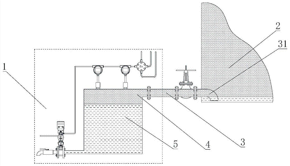
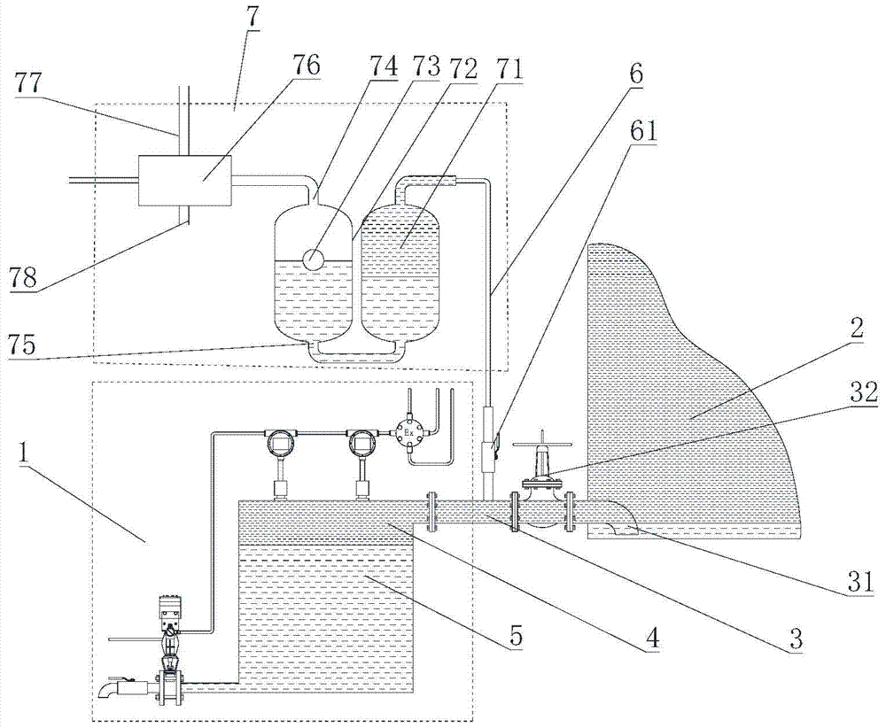
[0046] Such as figure 2 As shown, the breathing type automatic dehydration and oil return system for siphon oil tanks of the present invention includes a dehydrator 1, an oil tank 2, an oil return mechanism 7 and a main unit connecting the oil tank 2 and the dehydrator 1 Oil pipeline 3, at least a part of the dehydrator 1 is located below the oil tank 2, one end of the main oil pipeline 3 is arranged on the upper end of the dehydrator 1, the other end extends into the oil tank 2, and passes through the elbow 31 extends to the bottom of the oil tank 2, and the oil return mechanism 7 includes a first buffer tank 71 and a second buffer tank 72 whose bottoms communicate with each other, and a branch oil pipeline 6 connecting the first buffer tank 71 and the main oil pipeline 3 , the bottom of the second buffer tank 72 is provided with a first communication port 75 communicating with the bottom of the first buffer tank 71, and its top is provided with a first vent 74 communicating...

Embodiment 2

[0054] Such as image 3 As shown, in this embodiment, except that the oil return mechanism is different, other structures are the same as in Embodiment 1, and in this embodiment

[0055] The oil return mechanism includes a first buffer tank 81 and a second buffer tank 82 connected at the bottom, the top of the second buffer tank 81 is provided with a first vent hole 84, and its bottom is provided with a first communication port 85. A second liquid level controller 83 is arranged in the second buffer tank 82, and a liquid medium having a density higher than that of oil and not compatible with oil is housed in the second buffer tank 82. The liquid medium in this embodiment is water. The second liquid level controller 83 blocks the first communication port 85 or the first ventilation hole 84 along with the rise and fall of the water level in the second buffer tank 82 .

[0056] The branch oil pipeline 6 is provided with a control mechanism, and the control mechanism includes a T...

Embodiment 3

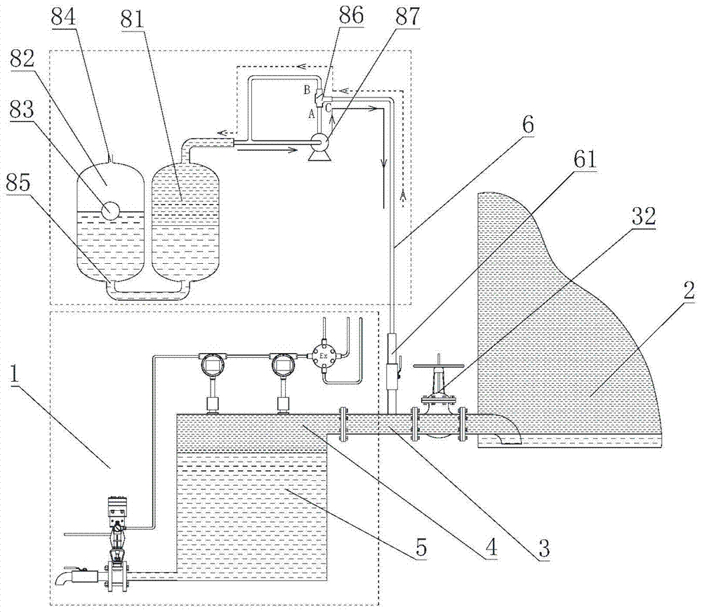
[0063] Such as Figure 4 As shown, except that the oil return mechanism of this embodiment is different from that of Embodiment 1, other structures and working principles are the same as those of Embodiment 1. The oil return mechanism includes a first buffer tank 91, a second buffer tank 92 and a first The buffer tank 91 and the first conduit 921 of the second buffer tank 92, the second buffer tank 92 is arranged above the first buffer tank 91, and one end of the first conduit 921 is arranged at the bottom of the second buffer tank 92, The other end extends to the bottom of the first buffer tank 91, and the first buffer tank 91 is provided with an input port near the top, and the first buffer tank 91 communicates with the main oil pipeline 3 by connecting the branch oil pipeline 6 through the input port , the second buffer tank 92 is equipped with a liquid medium with a density higher than that of oil, the liquid medium is water, and a third liquid level controller 93 is place...


PUM


Abstract

The invention discloses a respiration type automatic dehydration oil return system for a siphoning type oil tank. The respiration type automatic dehydration oil return system comprises the oil tank, a dehydrator, an oil return mechanism, and a main oil pipeline connecting the oil tank with the dehydrator. The oil return mechanism comprises a buffer tank, a branch oil pipeline connecting the buffer tank with the main oil pipeline, and a control mechanism. The buffer tank is filled with water, and the control mechanism is used for controlling oil in the dehydrator to flow into the buffer tank or controlling oil in the buffer tank to flow into the oil tank. Through reduction of the internal pressure of the oil return mechanism, the oil at the upper portion of the dehydrator is pumped out to the oil return mechanism, water at the bottom of the oil tank can flow into the dehydrator through the main oil pipeline, the dehydrator can continue conducting dehydration, if the dehydrator cannot conduct dehydration due to the increase of the oil content of the water, the oil in the oil return mechanism is drained out to the oil tank, the oil at the upper portion of the dehydrator is pumped, and dehydration is conducted cyclically. The respiration type automatic dehydration oil return system is high in automation degree, complete in dehydration, good in oil quality, high in dehydration efficiency and capable of being widely applied to the technical field of petrochemical oil tank dehydration.

Description

technical field [0001] The invention belongs to the technical field of petrochemical oil tank dehydration, and in particular relates to a breathing-type automatic dehydration oil return system and method for a siphon oil tank. Background technique [0002] Such as figure 1 As shown, the siphon oil tank dehydration oil return system includes an oil tank 2, a dehydrator 1, and a main oil pipeline 3 for connecting the oil tank and the dehydrator, and the main oil pipeline 3 is connected to the oil tank 1 in a downward bending Elbow 31, due to the obstruction of elbow 31, the oil that has entered the dehydrator 1 cannot automatically return to the oil tank 2, and the oil in the dehydrator must be manually drained to continue dehydration. The accuracy of oil discharge is not high, and the water content of oil is only judged subjectively by workers, which affects the quality of oil, and the dehydration efficiency is low, which cannot meet the requirements of modern people for oil...

Claims


Application Information

Patent Timeline
Patent Type & Authority Patents(China)
IPC IPC(8): B65D88/54B65D90/32B01D17/032
CPCB01D17/0214B65D90/32
Inventor 韩德福李鹏
Owner GUANGZHOU DAY WO AUTOMATION IND
Why Eureka
Try Eureka