Novel pneumatic semi-automatic end-connection control method and device of rotor spinning machine

A technology of rotor spinning machine and control device, which is applied in spinning machine, open-end spinning machine, continuous winding spinning machine, etc. The quality of the wire connector, the low manufacturing cost, and the effect of improving the success rate of the connector

Active Publication Date: 2015-01-21
JINGWEI TEXTILE MASCH CO LTD
View PDF6 Cites 4 Cited by
  • Summary
  • Abstract
  • Description
  • Claims
  • Application Information

AI Technical Summary

Problems solved by technology

[0003] The purpose of the present invention is to provide a new type of pneumatic semi-automatic joint control method for rotor spinning machines. Through the control of the electrical system, various functional solenoid valves can be completed in time sequence within the set time, and the joint action and joint can be accurately controlled. Time effectively overcomes the problems of low joint success rate and large error existing in the prior art

Method used


Image

  • Novel pneumatic semi-automatic end-connection control method and device of rotor spinning machine
  • Novel pneumatic semi-automatic end-connection control method and device of rotor spinning machine
  • Novel pneumatic semi-automatic end-connection control method and device of rotor spinning machine

Examples


Embodiment Construction

[0029] The preferred embodiments of the present invention will be further described in detail below in conjunction with the accompanying drawings:

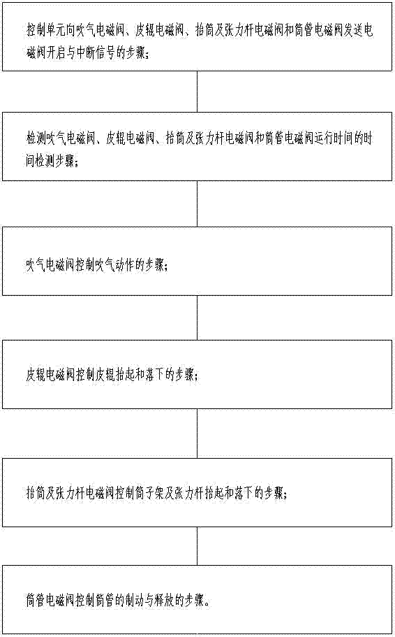
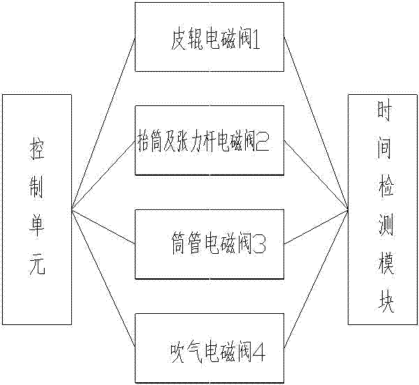
[0030] Such as figure 1 Shown is a step block diagram of a new type of pneumatic semi-automatic joint control method for a rotor spinning machine of the present invention. The method includes a control unit to blow solenoid valve 4, top roller solenoid valve 1, drum lift and tension rod solenoid valve 2 Steps of sending solenoid valve opening and interruption signals with the bobbin solenoid valve 3;

[0031] Time detection steps for detecting the running time of the air blowing solenoid valve 4, the top roller solenoid valve 1, the drum lift and tension rod solenoid valve 2, and the bobbin solenoid valve 3;

[0032] Steps of blowing solenoid valve 4 to control blowing action;

[0033] The top roller solenoid valve 1 controls the lifting and lowering steps of the top roller;

[0034] The lifting and tension rod solenoid valve 2 controls th...


PUM


Abstract

The invention relates to a novel pneumatic semi-automatic end-connection control method of a rotor spinning machine. The method includes the step that a blowing electromagnetic valve combination piece controls blowing motions, the step that a roller electromagnetic valve combination piece controls a roller to lift and fall, the step that a bobbin lifting and tension rod electromagnetic valve combination piece controls a bobbin creel to lift and fall and controls the tension rod to rotate, and the step that a bobbin electromagnetic valve combination piece controls a bobbin to brake and release. The device is compact in structure and convenient to install and adjust and is controlled by electric and pneumatic systems, and the motions can be controlled to be at a millisecond level; an integrated valve is formed through non-metal injection molding, manufacturing cost is low, and the motions are accurate and nimble; by means of the end-connection control method, the success rate of semi-automatic end connection and end-connection quality of yarn can be improved.

Description

Technical field [0001] The invention relates to a novel pneumatic semi-automatic joint control method and device for a rotor spinning machine, in particular to a pneumatic solenoid valve, a top roller solenoid valve, a drum lift and a tension rod solenoid valve and a drum controlled by an electric and pneumatic system The pipe solenoid valve completes the corresponding action according to the time sequence, so as to realize the pneumatic semi-automatic joint action. Background technique [0002] The rotor spinning machine is a fast-developing new type of spinning equipment. At present, the majority of user factories purchase domestically produced rotor spinning machines, and their semi-automatic splicing devices all use a combination of mechanical structure and electrical to complete the splicing process. When spinning splicing, the reliability is poor, the splicing success rate is low, and the error is large. The splicing success rate and yarn splicing quality have greater insta...

Claims


Application Information

Patent Timeline
Patent Type & Authority Applications(China)
IPC IPC(8): D01H4/48D01H4/08
CPCD01H4/08D01H4/48
Inventor 史文娟杨丕勇闫进祥何延军
Owner JINGWEI TEXTILE MASCH CO LTD
Why Eureka
Try Eureka